D-302413 NEXT PG2, NEXT K9-85 PG2 Installation Instructions 3
3. LOCAL DIAGNOSTICS TEST
NOTE: Run a diagnostic test at least once a year to ensure that the detector is working correctly.
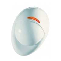
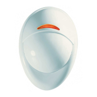
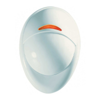
A. Separate the base from the cover (see Fig. 3).
B. Put back the cover to return the tamper switch to its normal (undisturbed) position, and then secure the front cover to the base with the
case closure screw.
C. The Next PG2 / Next K9-85 PG2 will enter a 2 min. stability period. During this time the red LED blinks.
D. Walk-test the coverage area - see Fig. 5. Walk across the far end of coverage pattern in both directions, The red LED lights each time
your motion is detected followed by 3 LED blinks.
The following table indicates received signal strength indication.
IMPORTANT! Reliable reception must be assured.
Therefore, "poor" signal strength is not acceptable. If you
receive a "poor" signal from the detector, re-locate it and
re-test until a "good" or "strong" signal strength is
received (in regions requiring UL-compliant installation,
only “strong” signal strength is permitted).
Notes:
1. For detailed Diagnostics Test instructions refer to the
control panel Installer Guide.
2. For UL/CUL installations, the test result must be
“Strong”.
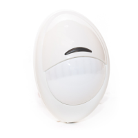
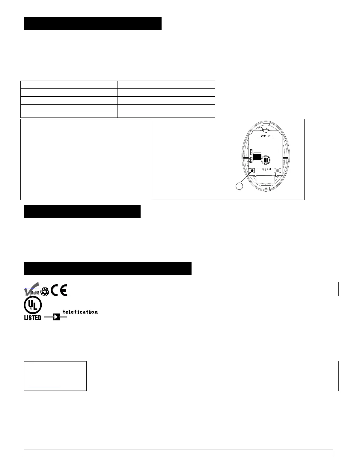
Figure 4. Device enroll button
4. SPECIAL COMMENTS
Even the most sophisticated detectors can sometimes be defeated or may fail to warn due to: DC power failure / improper connection,
malicious masking of the lens, tampering with the optical system, decreased sensitivity in ambient temperatures close to that of the human
body and unexpected failure of a component part.
The above list includes the most common reasons for failure to detect intrusion, but is by no means comprehensive. It is therefore
recommended that the detector and the entire alarm system be checked weekly, to ensure proper performance.
An alarm system should not be regarded as a substitute for insurance. Home and property owners or renters should be prudent enough
to continue insuring their lives and property, even though they are protected by an alarm system.
5. COMPLIANCE WITH STANDARDS
Compliance with Standards
Europe: EN 300220, EN 50131-1 Grade 2, Class II. EN 301489, EN 50130-4, EN 60950, EN 50131-2-2,
EN 50131-6 Environmental IP55.
The NEXT PG2 and NEXT K9-85 PG2 are compatible with the RTTE requirements - Directive 1999/5/EC
of the European Parliament and of the Council of 9 March 1999 and EN50131-1 Grade 2 Class II.
Certified by the Dutch testing and certification body Telefication BV to the following standards :
EN 50131-2-2, EN 50131-6, EN 50131-5-3, EN 50130-4, and EN 50130-5.
Telefication BV has certified only the 868 MHz variant of this product.
Also complies to USA: CFR47 Part 15; Canada: RSS 210;
UK: This product is suitable for use in systems installed to conform to PD6662:2010 at Grade 2 and environmental class 2. DD243 and BS8243.
The Power G peripheral devices have two- way communication functionality, providing additional benefits as described in the technical brochure. This functionality has
not been tested to comply with the respective technical requirements and should therefore be considered outside the scope of the product’s certification.
EN 50131-1 Security Grade
According to EN 50131-1:2006 and A1:2009, this equipment can be applied in installed systems
up to and including Security Grade 2.
EN 50131-1 Environmental Class
This device has been tested and found to comply with the limits for a Class B digital device, pursuant to Part 15 of the FCC Rules. These
limits are designed to provide reasonable protection against harmful interference in residential installations. This equipment generates uses
and can radiate radio frequency energy and, if not installed and used in accordance with the instructions, may cause harmful interference to
radio and television reception.
However, there is no guarantee that interference will not occur in a particular installation. If this device does cause such interference, which can be
verified by turning the device off and on, the user is encouraged to eliminate the interference by one or more of the following measures:
– Re-orient or re-locate the receiving antenna.
– Increase the distance between the device and the receiver.
– Connect the device to an outlet on a circuit different from the one that supplies power to the receiver.
– Consult the dealer or an experienced radio/TV technician.
WARNING! Changes or modifications to this unit not expressly approved by the party responsible for compliance could void the user’s
Visonic Ltd.
M/N: RFD
FCC ID: WP3RFD
IC: 1467-RFD
 Loading...