Do you have a question about the Viva SKYLO and is the answer not in the manual?
First check for any obvious manufacturing defects like cracks.
Check that all listed parts are present before installation.
Ensure the entire installation guide is followed meticulously.
Cistern pressure should be 0.2-8.0 bar; use a pressure reducing valve if higher.
Pipework must be free from debris before commencing installation.
Do not use plumber's putty or silicone sealant on any fittings.
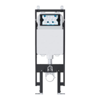
Ensure the mounted surface can support the cistern's full weight (approx 8kg).
Faults occurring due to operation outside recommended water pressure limits.
Damage that is found to have been caused after delivery to the site.
Damage from bleach or cleaners; in-tank cleaners may cause product failure.
Faults that arise due to incorrect or poor installation practices.
Faults caused by particles like dirt, silt, silicone, or plumber's putty.
Any loss or damage that is a consequence of product failure.
Insert the drain connector clip into the frame and slide to lock it.
Insert the drain connector into the soil pipe; angled connectors are optional.
Loosen the height adjustment bolts on the frame using a wrench or spanner.
Position the frame correctly into its designated installation area.
Measure from the sub floor to mark the intended finished floor level on a joist.
Align the frame's 1m indicator with the 1m mark on the joist from the FFL.
Tighten the height adjustment bolts on frame legs and check for slippage.
Details the frame's 75mm depth and two fixing options for various wall types.
Measure and cut wall fixing bolts 5mm shorter than the wall void depth.
Offer up wall fixing brackets behind frame and screw bolts into them.
Mark the wall for drilling holes, ensuring brackets are upright.
Ensure frame feet are flush with joists, then mark sub-floor for drilling.
Drill two 10mm holes at marked wall locations and insert raw plugs.
Drill two 10mm holes at marked sub-floor locations and insert raw plugs.
Place frame back and secure to wall and floor using supplied screws.
Adjust the frame's level using adjustment bolts to ensure it is plumb.
Place locking clips onto bolts, tighten A against frame and B against bracket.
Ensure the frame is level and adjust legs accordingly if necessary.
With feet flush to joists, ensure the frame is plumb.
Mark the 4 frame hole locations and the locations for the feet holes.
Carefully set the frame to one side after marking.
Drill 5mm pilot holes at each marked location on the studs.
Secure the frame to the wall studs using the supplied screws.
Tighten the securing screws using a socket wrench or spanner.
Remove the inspection plate by pinching the clips at the top.
Connect the water supply to the 1/2" thread on the cistern's top right.
Ensure the isolation valve is closed by twisting it fully to the right.
Lock the drain connector clip around the drain connector securely.
Insert flush pipe and drain connector blanks into their corresponding outlets.
Insert toilet hanging threads (180/230mm) and slot sheaths over them.
Attach the cover over the inspection plate to prevent debris entry.
Remove the cover cap prior to completing the wall installation.
Cover the stud wall with plasterboard, cutting holes for outlets.
Re-attach the inspection cover plate before tiling the wall.
Complete the wall finishing by applying tiles and grout.
Remove the flush pipe and drain connector blanks.
Remove or cut the toilet bolt sheaths as required.
Insert pan connector and flush pipe onto the toilet, marking line with back edge.
Insert connectors into wall outlets, marking line flush with finished tiles.
Measure gap between lines and cut connectors to the same length.
File a small chamfer onto the cut ends of connectors for smooth touch.
Lubricate cut connector ends and insert them fully into wall outlets.
Locate the wall protector membrane and hang it against the wall.
Place the pan onto the bolts, ensuring it is held level.
Secure the pan on both sides with plastic washer, metal washer, and nut.
Tighten the pan fixing bolts on both sides using a socket wrench.
Place the blanking caps onto the ends of the pan fixing bolts.
Cut the wall membrane around the outer edge of the toilet and discard excess.
Once satisfied, seal the rear edge of the toilet with silicone sealant.
Cut and discard the corrugated part of the cover flush with the wall tiles.
Remove inspection cover and turn on the water using the isolation valve.
Attach the flush plate bracket using the rods provided.
Rotate the clips as shown to lock and secure the bracket.
Break off central button rods if necessary, depending on wall depth.
Insert central button rods and secure by twisting rod wings vertically.
Apply the flush button, first to lower clips, then to the top edge.
The left button is for full flush, the right button is for half flush operation.
| Brand | Viva |
|---|---|
| Model | SKYLO |
| Category | Plumbing Product |
| Language | English |