EN - 6
General Connection (without PoE)
Network Deployment
4
POW
ER
C
OLL
I
S
ION
L
I
N
K
RE
CEIVE
PARTITIO
N
1
2
3
4
5
1. If you have external DI devices, make the connection from general I/O terminal block.
2. Ethernet, power, and other cables are user-supplied.
3. Connect the AC cables from the terminal block as an alternate power source. The IO
cables are user-supplied.
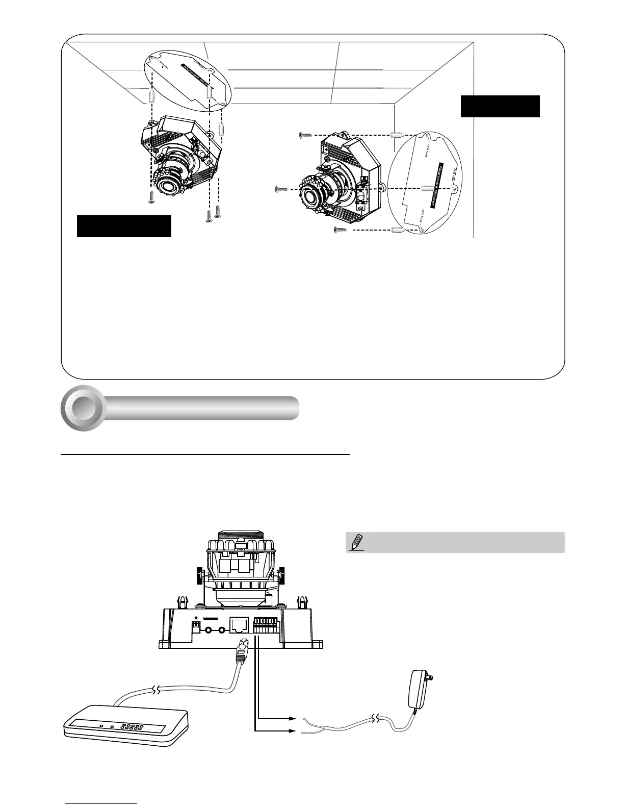
1. Attach the alignment sticker to the ceilling/wall.
2. Through the two circles on the sticker, drill two pilot holes into the ceilling/wall.
3. The Network Camera can be mounted with the cable routed through the ceiling/wall or
from the side. If you want to feed the cable through the ceiling/wall, drill a cable hole A
as shown in the above picture.
4. Hammer the supplied plastic anchors into the holes.
5. Align the two holes on each side of the camera base with the two plastic anchors on the
ceilling/wall, insert the supplied screws to corresponding holes and secure them with a
screwdriver.
Wall Mount
Ceiling Mount
Ethernet
Switch
Pin1 & 2 AC 24V
Pin #1 & 2 AC 24V as alternate power are for
indoor use only
NOTE:
 Loading...