VIVOTEK
User's Manual - 129
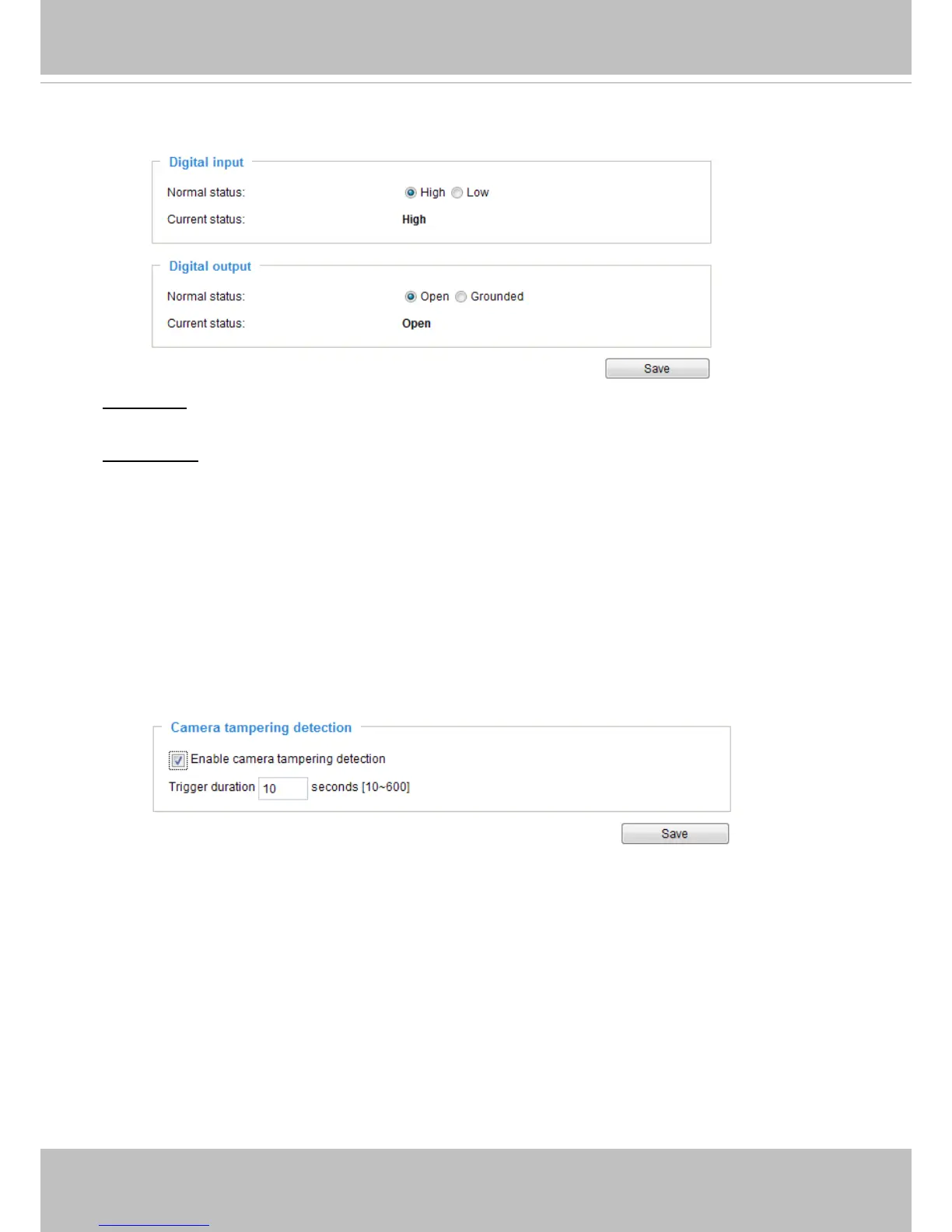
Applications > DI and DO
Digital input: Select High or Low as the Normal status for the digital input. Connect the digital input pin of
the Network Camera to an external device to detect the current connection status.
Digital output: Select Grounded or Open to dene the normal status for the digital output. Connect the
digital output pin of the Network Camera to an external device to determine the current status.
Set up the event source as DI on Event > Event settings > Trigger. Please refer to page 112 for
detailed information.
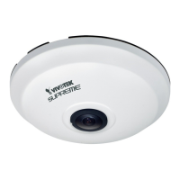
Applications > Tampering detection
This section explains how to set up camera tamper detection. With tamper detection, the
camera is capable of detecting incidents such as redirection, blocking or defocusing, or even
spray paint.
Please follow the steps below to set up the camera tamper detection function:
1. Check Enable camera tampering detection.
2. Enter the tamper trigger duration. (10 sec. ~ 10 min.) The tamper alarm will be triggered only when the
tampering factor (the difference between current frame and pre-saved background) exceeds the
trigger threshold.
3. Set up the event source as Camera Tampering Detection on Event > Event settings > Trigger.
Please refer to page 112 for detailed information.