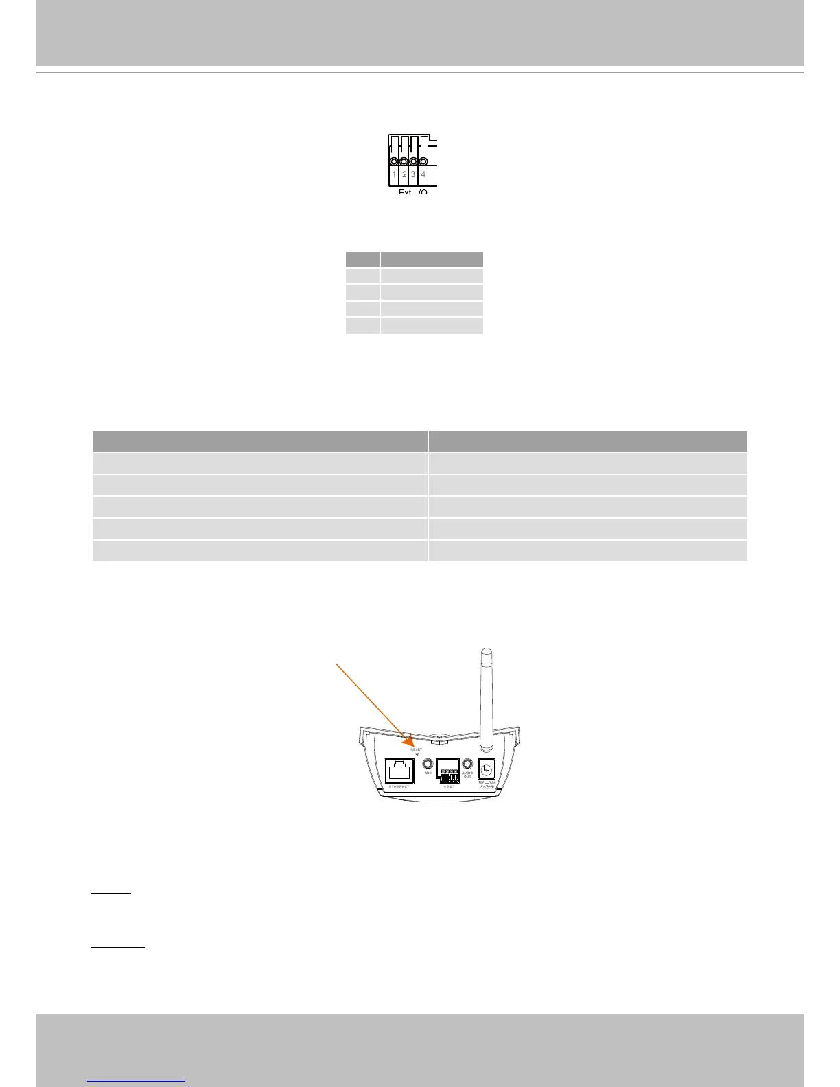
General I/O Terminal Block
This Network Camera provides a general I/O terminal block which is used to connect external
input / output devices. The pin denitions are described below.
Status LED
The color of LED indicates the status of the Network Camera�
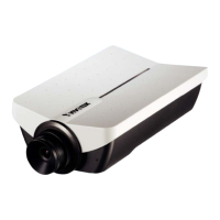
Hardware Reset
The reset button is used to reset the system or restore the factory default settings� Sometimes
resetting the system can return the camera to normal operation� If the system problems remain
after reset, restore the factory settings and install again�
Reset: Press and release the indented reset button with a paper clip or thin object� Wait for the
Network Camera to reboot�
Restore: Press and hold the reset button until the status LED rapidly blinks� It takes about 30
seconds� Note that all settings will be restored to the factory default�
Pin Name
1 Digital output
2 Digital input
3 DC power
4 Ground
Status LED color Description
Steady green and blink red (once) Loading system after power on
Steady green During booting procedure
Steady orange (green + red) till IP address is confirmed Detecting and setting network
Blink green / orange every second and steady red After network is setup (system up)
Blink orange every second and fast blink red During the upgrade firmware process