VIVOTEK
User's Manual - 25
Network Deployment
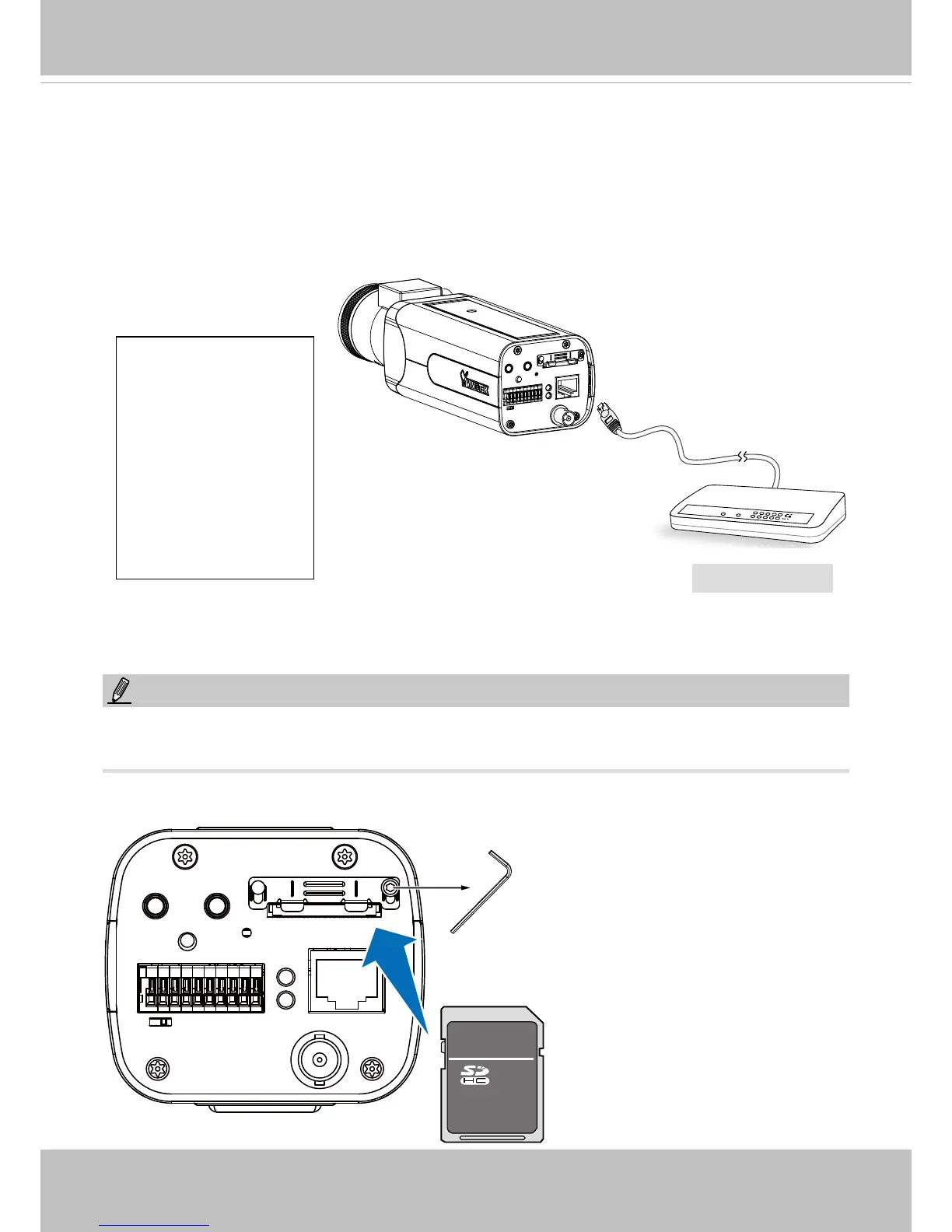
General Connection (with PoE)
4. If you have external devices such as sensors and alarms, connect them to the general I/O
terminal block. Install the camera base to the mounting hole at the bottom of the camera.
5. Connect the camera to a switch using an Ethernet cable.
1. DO+
2. DO-
3. DI1+
4. DI2+
5. DI3+
6. DI- (common GND)
7. RS485-
8: RS485+
9. AC/DC pw
10. AC/DC pw
NOTE:
• The camera is only to be connected to PoE networks without routing to outside plants.
• For PoE connections, use only UL listed I.T.E. with PoE output.
POWER
COLLISION
LINK
RECEIVE
PARTITION
1
2
3
4
5
TM
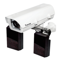
6. Use the included hex wrench to access the SD card socket. Install an SD card.
PoE Switch