6 7
Installation
PRE-INSTALLATION
Below are the services required to be in place prior
to the installation of the Vivreau ViTAP Dispensing
System. If you have any questions regarding these
or other services, please contact Vivreau Service
Toll-Free at 877-999-1044.
WATER SUPPLY
A potable 1/2” cold water supply terminating in a
1/2” Ball Valve, 1/2” female pipe thread.
IMPORTANT ________________________
Ball Valve must be accessible for service
and installation.
Minimum Water Pressure: 50 PSI
Minimum Water Flow: 80 gallons per hour
IMPORTANT ________________________
The Vivreau ViTAP Dispensing System
incorporates backow prevention. Any additional
backow devices required by State or Local
Code must also be supplied by the customer
prior to installation. There must not be any
other Filters/Pre-Filters inline before the unit.
ELECTRICAL OUTLET
Model ViTAP-2
(1) 20 Amp Electrical Recepticle (NEMA 5-20R)
120V, 60 Hz (11 Amps)
Model ViTAP-2H
(2) 20 Amp Electrical Recepticle (NEMA 5-20R)
120V, 60 Hz (11 & 13 Amps)
Model ViTAP-1
(1) 20 Amp Electrical Recepticle (NEMA 5-20R)
230V, 60 Hz (11 Amps)
Model ViTAP-1H
(2) 20 Amp Electrical Recepticle (NEMA 5-20R)
230V, 60 Hz (11 Amps)
All outlets must be mounted high in the cabinet to
avoid accidental contact with water.
CO
2
CO
2
Cylinder (Customer supplied) - Size should be
selected based on available space.
NOTE: If connecting to a bulk or existing CO
2
system, a CO
2
line terminating at a 1/4” Barbed
Shutoff Valve must be available within 40” of the
unit with 100 PSI minimum pressure.
DRIP TRAY AND DISPENSING HEAD
CUTOUTS
Cut out the holes for the Drip Tray and Dispensing
Head per the supplied template.
NOTE: The Dispensing Head must be mounted
on the work surface directly above the Chiller/
Carbonator.
DRIP TRAY DRAIN
Drip Tray must be plumbed to a drain. Customer
will need to supply a drain according to State and
Local Codes. Drain must be at least 1-1/4” ID.
VENTILATION
If the system is to be installed in an enclosed
space or in a cabinet, adequate ventilation must
be provided. Ventilation must be at the top and
bottom of the enclosure for proper air ow.
Failure to provide adequate
ventilation will cause system failure.
This unit is to be installed indoors only.
LOCATION OF SERVICES
All services must be accessible for installation and
service. Ensure all services are kept within 40” of
the Vivreau ViTAP Dispensing System.
Water Shutoff Valve to be located at low level.
Ensure there is sufcient room for a 6” long tting to
be connected to the Water Shutoff Valve.
Top of drain should be located between 12” and
18” from oor level.
SHIPPING DAMAGE/MISSING PARTS
Unpack and inspect the unit for shipping damage
and/or missing parts. If any damage or missing
parts are found, contact Vivreau Service Toll-
Free at 877-999-1044 and report the missing or
damaged parts.
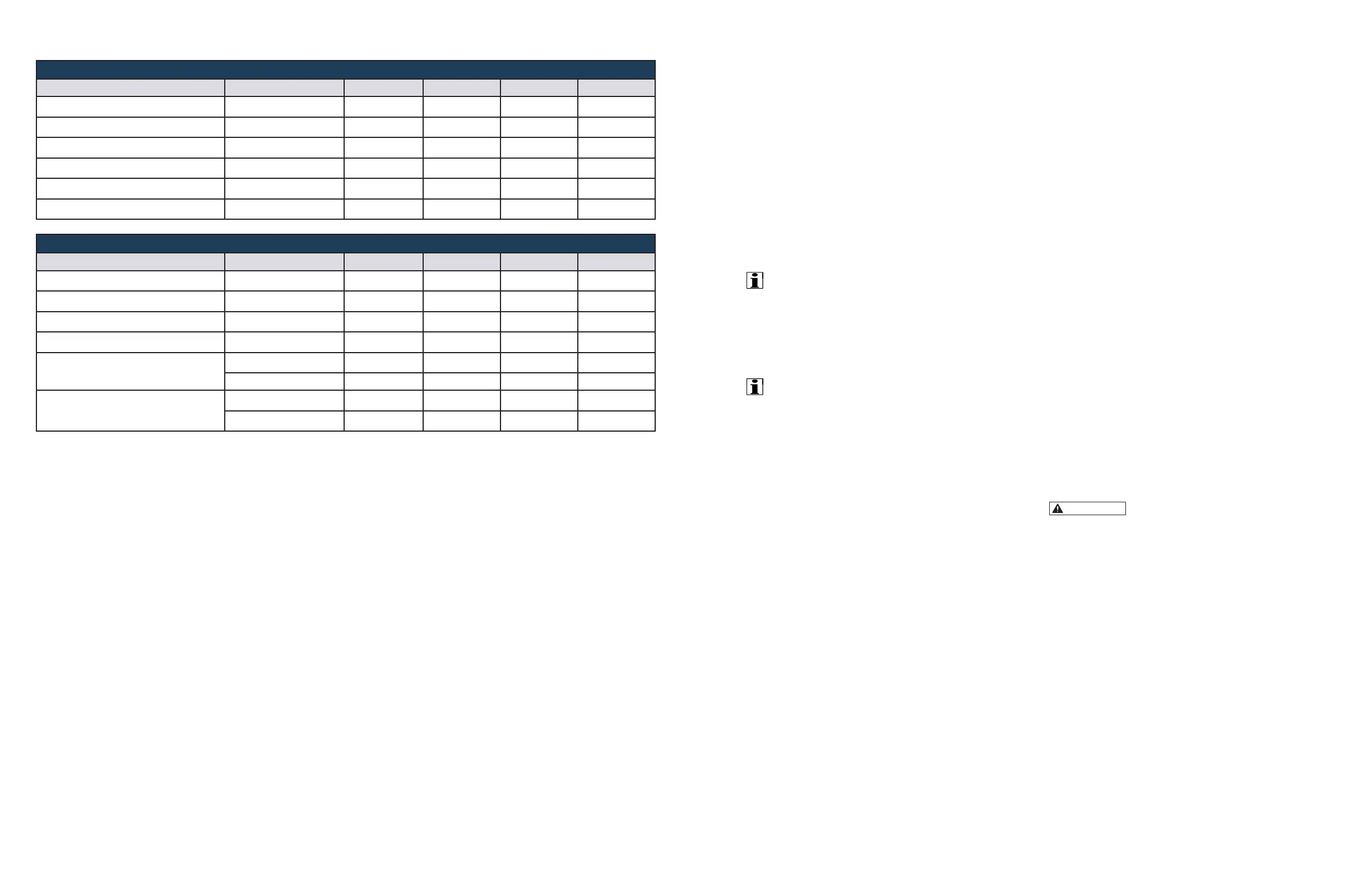
Cooler/Carbonator Specications
Description Specication ViTap-2 ViTap-2H ViTap-1 ViTap-1H
Width
15”
ü ü
8.25” 8.25”
Height
20”
ü ü
19” 19”
Depth
18.5”
ü ü
14" 14”
Weight
39.6 lb.
ü ü
44.6 lb 44.6 lb
Voltage
110/120 VAC/60 Hz
ü ü ü ü
Amperage
11A
ü ü ü ü
Boiler Specications
Description Specication ViTap-2 ViTap-2H ViTap-1 ViTap-1H
Width
5.25” NA
ü
NA 5.37”
Height
22” NA
ü
NA 21”
Depth
15.75” NA
ü
NA 15.62”
Weight
30.8 lb NA
ü
NA 18.2 lb
Voltage
110/120 VAC/60 Hz NA
ü
NA 120 V
230/240 VAC/60 Hz NA NA NA 240 V
Amperage
13A NA
ü
NA
ü
11A NA NA NA
ü
 Loading...