8 9
INSTALLER’S CHECKLIST
Below are the services required to be in place prior
to the installation of the Vivreau ViTAP Dispensing
System. Please review and check all services
before beginning work. If anything is missing or not
correct, do not start the installation. Call Vivreau
Service for instructions at 877-999-1044.
WATER SUPPLY
A potable 1/2” cold water supply terminating in a
1/2” Ball Valve, 1/2” female pipe thread.
IMPORTANT ________________________
Ball Valve must be accessible for service and
installation.
Any water line or valve less than 1/2” is not
acceptable. Must be a direct supply with no
other Inline Filters.
ELECTRICAL OUTLET(S)
All Electrical Outlets must be within 40” of unit. No
Extension Cords.
Model ViTAP-2
Chiller/Carbonator
20 Amp Electrical Recepticle (NEMA 5-20R)
120V, 60 Hz (11 Amps)
Model ViTAP-2H
Chiller/Carbonator
20 Amp Electrical Recepticle (NEMA 5-20R)
120V, 60 Hz (11 & 13 Amps)
Boiler
20 Amp Electrical Recepticle (NEMA 5-20R)
120V, 60 Hz (11 & 13 Amps)
Model ViTAP-2HD
Chiller/Carbonator
15 Amp Electrical Circuit (NEMA 5-15) 120V, 60
Hz
Boiler
20 Amp Electrical Circuit (NEMA L6-20) 230V, 60
Hz
Model ViTAP-1
Chiller/Carbonator
20 Amp Electrical Recepticle (NEMA 5-20R)
230V, 60 Hz (11 Amps)
Model ViTAP-1H
Chiller/Carbonator
20 Amp Electrical Recepticle (NEMA 5-20R)
230V, 60 Hz (11 Amps)
Boiler
20 Amp Electrical Recepticle (NEMA 5-20R)
120V, 60 Hz (11 & 13 Amps)
CO
2
CO
2
Cylinder (Customer supplied) must t within
the allotted space.
CO
2
Cylinder must always remain vertical.
If connecting to a bulk or existing CO
2
system, a
CO
2
line terminating at a 1/4” Barbed Shutoff Valve
must be available within 40” of the unit with 100
PSI minimum pressure.
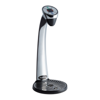
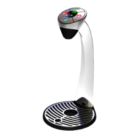
DRIP TRAY AND DISPENSING HEAD
CUTOUTS
Cut out the Holes for the Drip Tray and Dispensing
Head per the template.
The Dispensing Head must be mounted on the
work surface directly above the Chiller/Carbonator.
The Dispensing Head lines must never be
extended.
DRIP TRAY DRAIN
Drip Tray must be plumbed to a drain. Customer will
need to supply a properly trapped drain according
to State and Local Codes. The drain must be large
enough to accommodate a 1” OD exible pipe.
VENTILATION
If the system is to be installed in an enclosed
space or in a cabinet, adequate ventilation must
be provided. Ventilation must be at the top and
bottom of the enclosure for proper air ow.
Failure to provide adequate
ventilation will cause system failure.
This unit is to be installed indoors only.
INSTALLATION
IMPORTANT ________________________
Installation must be performed by properly
trained and qualified persons and comply with
Federal, State Local Codes for connection
to electrical supplies, water supplies and
pressurized gas systems.
Note: Vivreau cannot be held responsible for any
damage caused by improper installation.
LOCATION
A completed Pre-installation Checklist must be
available prior to installation. The Vivreau ViTAP
Dispensing System must be installed indoors
where the ambient air temperature will not exceed
90°F.
The Vivreau ViTAP Dispensing System should not
be exposed to spills, spray, steam or high humidity.
A suitable location should be chosen within 40” of
the electrical and water supply connections.
Installation Clearance for Chiller Unit
Left side 2”
Right side 2”
Rear 2”
Above Open
Do not obstruct air vents.
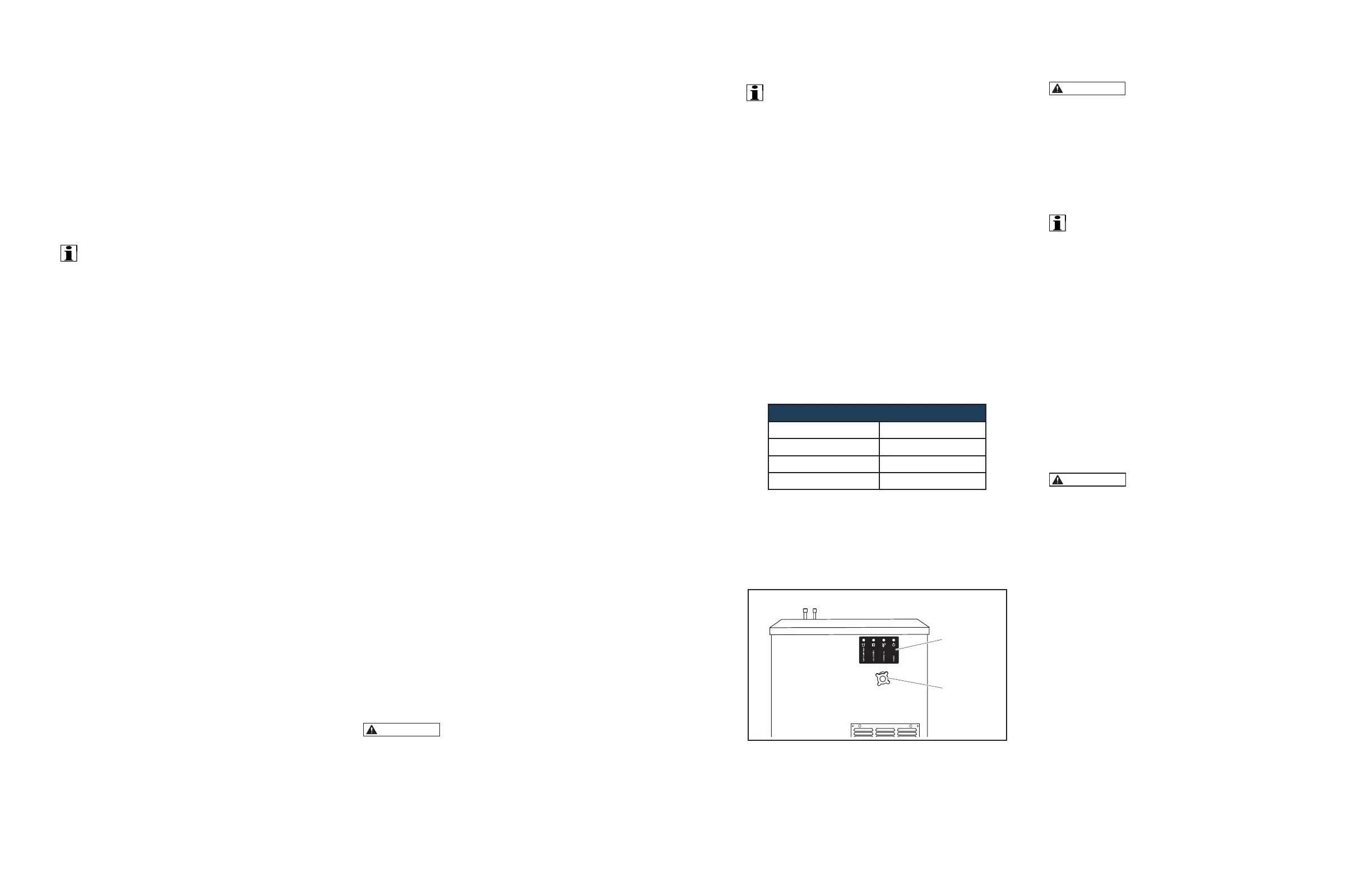
Install the system on a rm, level oor or base.
Chiller/Carbonator should be installed with LED
Panel and Overow Drain Tube facing out for
visibility and ease of access.
CONTROL PANEL FACING FRONT
LED Panel
Overflow
Drain Tube
Plug
LED Panel and Overow Drain Tube Plug Location
CONNECTIONS
This appliance must be
electrically grounded.
ELECTRICAL
Power Supply: 120V 60Hz
Power Supply Connection Type: NEMA 5-20
Grounded, with proper circuit protection.
IMPORTANT ________________________
When a Carbonator is used – follow the
Carbonator’s installation instructions.
CO
2
Mount the CO
2
Regulator in a secure location
where it will not be subject to damage.
A Cylinder of food-grade CO
2
gas is required. Only
use non-syphon type Cylinders.
NOTE: Before connecting, with the Cylinder Outlet
turned away, open Valve for short blast and close
immediately. This will clear any debris from the
outlet.
CO
2
Cylinder must be installed vertically and
secured with a Chain, Strap or Bracket.
CO
2
Cylinders should always be
secured in the vertical position with the Outlet
Valves positioned at the top. This will help
prevent injury caused by the entry of liquid
Carbon Dioxide into the Pressure Regulator.
 Loading...