10 11
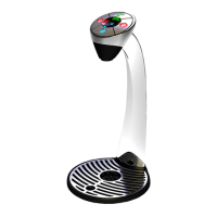
Never open the Gas Cylinder
Dispensing Head without the Gas Regulator
installed.
Ensure the Sealing Washers are positioned
between the Gas Regulator / Regulator Hose and
Cylinder and connect the Cylinder.
Regulator
Sealing
Washers
CO2 Cylinder
Sealing Washer Locations
Connect the Regulator to the unit using the supplied
Installation Kit. Tighten all connections.
In the event of a CO
2
leak, close the Cylinder Valve,
retighten connection(s) and retest. If leak persists,
report leak to Vivreau.
CO
2
Pressure: 65 – 70 PSI. Adjust Regulator as
needed.
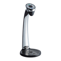
WATER
The Vivreau ViTAP Dispensing System provides
backflow prevention, however, it must be installed
with adequate backflow protection to comply
with applicable Federal, State and Local Codes.
Additional backflow prevention must be installed
prior to connecting the unit to the water supply.
The water supply to the unit must be cold, potable
water with an accessible Shutoff Valve.
Water Inlet connection to the unit is 3/8” tube. A
Retaining Clip must be used to attach the tube
within the connection on the unit.
Insulate the pipe to prevent condensation.
The supply water pressure must be 50 PSI minimum
with a minimum ow of 1.5 gal/min. A Booster Pump
(for low pressure) or Pressure Regulator (for high
pressure) may be required to ensure the pressure.
1/2"
Shutoff
Valve
Water
Block
Insulate Pipe
Dual Check
Valve
3/8"
Connection
To
Chiller/
Carbonator
Water Connections
WATER BLOCK
A device called a Water Block (supplied by
Vivreau), must be installed between the Water
Supply Shutoff Valve and the Water Inlet to the unit.
This device is normally open but will close
automatically after it senses a continuous ow of
about 1.5 gallons.
UNDER-COUNTER INSTALLATION
The Under-Counter Chiller/Carbonator System
is intended to be located directly under the
Dispensing Head.
The Drip Tray is positioned in the counter under
the Dispensing Head and should have lateral play
of no more than 1/8”.
Dispensing Head Connection Tubes are to be
connected to the Under-Counter System directly
using the Installation Kit supplied by Vivreau.
FILLING THE WATER TANK
Disconnect unit from electrical
power supply.
Before making the nal water connection to the unit:
Remove the Overow Plug on the front of the unit.
Prop the back of the unit up about 1”.
Slowly ll the Water Tank using the Water Supply Line.
Catch any water that overows.
Remove
Overflow
Drain
Tube Plug
Water
Supply
Line
Drain Overow
Level the unit.
Replace the plug.
Connect Water Supply Line to unit.
Clean up any spills.
Do not leave the Water Hose
unattended while filling.
Make sure no water spills onto electrical
components.
Unless approved by Vivreau, do not use
de-ionized water or add any substance to the
water.
The installer must stay on site
until a full icebank has formed. Water will be
displaced and exit from the overflow.
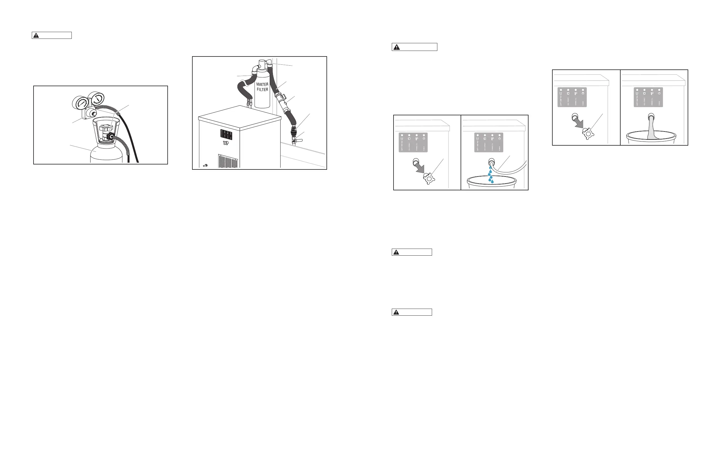
OVERFLOW
The Overow Drain will pass water displaced by the
formation of the icebank on initial thermal pulldown.
This water must be collected and drained.
Remove
Overflow
Drain
Tube Plug
Remove Overow Drain Tube Plug
Remove the Overow Drain Tube Plug and catch
any water draining from the Overow Tube.
Replace plug.
BOILER INSTALLATION
Vi Tap-2H and Vi Tap-1H
Electrical Installation:
Connect to 110-120 VAC Circuit with a NEMA
5-20 Plug.
This unit must be connected to a Grounded Outlet.
Refer to Rating Plate for further electrical
information.
 Loading...