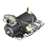
The VMC PACK SMART V90C (C40P) is an integrated air compressor system designed for use in various industrial applications. It features patented valves for both piston and screw rotary compressors, ensuring efficient and reliable operation.
Function Description
The PACK SMART V90C (C40P) is a volumetric screw compressor with two oil-injected screws. It integrates several key components into a single unit: a screw compressor, an intake valve, an oil separator tank, a minimum pressure valve, and a thermostatic valve. This compact design simplifies installation and maintenance within larger machinery or as part of a complete compressor system. The unit is designed to be installed inside a machine or assembled with other machines, forming part of a larger machinery system. It is crucial that the machinery in which it is installed complies with Directive 2006/42/EC before the PACK SMART V90C is put into service.
Important Technical Specifications
General:
- Type of machine: Oil-injected rotary screw compressor
- Drive: Direct or belt
- Rotor dimension (Outside main diameter): 89.4 mm (3.5 in)
- Rotor dimension (L/D): 1.55
- Air capacity (ISO 1217 annex B 2009): 0.76-3.83 m³/min (26.8-135.3 cfm)
- Max Working Pressure: 13 bar g (188.5 psi g)
- Min Working Pressure: 5 bar g (72.5 psi g)
- Oil injected quantity: 29-40 l/min (7.66-8.79 gal/min)
- Max input Power: 22 kW (29.5 hp)
- Max main rotor speed: 8100 rpm
- Min main rotor speed: 2000 rpm
- Max outlet air/oil temperature: 105 °C (221 °F)
- Environment max. Temperature: 45 °C (113 °F)
- Environment min. Temperature: 0 °C (32 °F) (For temperatures below 15°C / 59°F, ISO VG 32 lubricant is recommended.)
- Thermostatic temperature: 55-71-83 °C (131-159.8-181.4 °F)
- Gear ratio: 0.95 min / 2.55 max
- Oil nipple size: 3/4 Gas - 3/4 16UNF – 1" 12UNF
- Separator nipple: M39x155mm - M32x137mm
- Operating pressure: 8bar - 10bar - 13bar
- Materials:
- Air-end body: cast iron
- Body valve: Aluminium
- Internal parts: Aluminium galvanized, stainless steel, PTFE, viton, Xylan
- Weight: 69.7 Kg (153.7 lb)
Dimensions (International System - mm):
- Overall length: 559 mm
- Overall width: 274 mm
- Overall height: 317 mm
- Mounting holes: 4 x Ø13.50 mm
Dimensions (U.S. Unit System - inches):
- Overall length: 22 inches
- Overall width: 10.79 inches
- Overall height: 12.48 inches
- Mounting holes: 4 x Ø0.53 inches
Usage Features
Installation:
- Ensure the intake valve is not clogged by foreign particles.
- All connections to the radiator must be correctly linked to prevent air and oil leaks.
- The radiator's sizing must ensure correct thermal flow. Minimize the internal volume of the radiator to avoid harmful oil level fluctuations in the tank.
- Securely fix the compressor to the machine base using the designated fixing holes.
- When painting the integrated system, protect the identification plate, gaskets, intake holes, external threads, and all sealing surfaces from solvents or paints.
- Use cylindrical GAS threaded fittings; tapered GAS threaded fittings can damage the Pack Smart.
- Motor Connection: Verify that the rotation direction of the electric motor matches the arrow indicated on the air-end body (clockwise). Incorrect rotation can damage the air-end.
- Belt Drive: If belt-driven, ensure pulleys are aligned and belts are correctly tensioned. For "POLY V" belts, recommended tension should not exceed 1500 N. The pulley fitted to the air-end shaft should have a diameter of at least 70 mm (2.76 inches). Excessive belt tension shortens bearing life.
- Direct Drive with Coupling: If direct-driven, use a flexible coupling with individual elastic elements. The coupling must not be lubricated. Ensure motor and air-end shafts are correctly aligned.
- Protect transmission parts (couplings, pulleys) to prevent accidents once the machine is running.
First Start:
- Before starting, inject approximately 0.8 liters (0.02 gallons) of lubricant into the intake valve's air inlet by pressing down the throttle and manually rotating the rotors in the correct direction. Be careful not to damage the throttle seal O-ring.
- Fill the oil tank with mineral lubricant up to the level indicated by the viewer (approximately 10 liters / 0.74 gallons).
- Run the compressor for about 5 minutes to circulate the lubricant through the system (pipes, radiator, filters, etc.).
- Turn off the compressor, discharge pressure, and top up the lubricant to the indicated level.
Synthetic Oil Use:
- If switching to synthetic lubricants, first inject approximately 0.4 liters (0.01 gallons) of synthetic lubricant into the intake valve's air inlet, pressing the throttle and manually rotating the rotors.
- Drain the mineral oil already in the circuit through the drain plug.
- Fill the tank with synthetic lubricant to the specified level.
- Run the compressor for about 5 minutes to circulate the lubricant.
- Turn off the compressor, discharge pressure, and drain all synthetic oil from the system.
- Refill the tank with new synthetic oil to the specified level.
- Run the compressor for about 5 minutes.
- Turn off the compressor, discharge pressure, and top up the lubricant to the specified level.
- Warning: Failure to perform this "washing cycle" can lead to lubrication problems due to incompatible lubricant mixing.
Minimum Pressure Valve Calibration:
- To increase pressure: Unscrew the stop nut (B2) and slowly screw in the pressure control screw (B). Once the desired minimum pressure is reached, tighten the stop nut (B2).
- To decrease pressure: Unscrew the stop nut (B2) and slowly unscrew the pressure control screw (B). Once the desired minimum pressure is reached, tighten the stop nut (B2).
Long Periods of Inactivity:
- If the compressor is inactive for more than one week, it is recommended to start it in idle mode for about 5 minutes to ensure optimal system lubrication.
Maintenance Features
General Safety:
- Always read the manual carefully before any operation.
- Installation and maintenance must be performed by qualified personnel, adhering to safety regulations.
- Wear appropriate protective clothing (overalls, gloves, safety glasses, earplugs, etc.) during installation and maintenance.
- All installation and maintenance operations must be performed with the machine switched off (ambient pressure) and the electrical circuit disconnected.
- Do not touch moving parts when the machine is in operation.
- Equipment used for handling must be adequately sized for weight and geometry. Protruding parts must be protected.
Troubleshooting:
The manual provides a comprehensive troubleshooting list for common issues:
- Compressor doesn't load:
- Intake valve remains closed: Check/replace valve or spare parts kit.
- Solenoid valve not working: Check/replace solenoid valve.
- Losses on pressure line: Check/repair pipes and connections.
- Compressor does not discharge pressure from separator tank during idling:
- Solenoid valve not working: Check/replace solenoid valve.
- Calibrated nozzle clogged: Clean/replace nozzle.
- Compressor capacity or pressure lower than usual:
- Air filter clogged: Clean/replace air filter.
- Intake valve not opening: Check/replace valve or spare parts kit.
- Air loss from safety valve: Replace valve.
- Compressor keeps on loading over working pressure (safety valve opens):
- Solenoid valve not working: Check/replace solenoid valve.
- Clogged separator filter: Replace separator filter.
- Compressor overheating:
- Insufficient cooling: Check cooling system, coolant level.
- Dirty oil: Replace with new oil.
- Oil level too low: Check/add oil.
- Clogged cooler or pipe connection: Clean cooler and pipes.
- Thermostatic valve not working: Check/replace valve or K17 spare parts kit.
- Clogged oil filter: Replace oil filter.
- Oil leakage from intake valve only when machine is switched off (oil soaked-up air filter):
- Intake valve not working properly (not closing): Check/replace valve or K9 spare parts kit.
- Non-return valve of intake valve not working correctly: Check/clean it.
- Oil soaked-up air filter during unloading phase:
- Too high oil level in tank: Check oil level on separator tank.
- Clogged separator filter: Replace separator filter.
- Recovery oil viewer dirty or not working: Clean/replace viewer or K15 spare parts kit.
- Compressor remains under loading phase:
- Intake valve not working properly (not closing): Check/replace valve or spare parts kit.
- Rotor seizure:
- Unknown particles inside: Call VMC technical support.
- Insufficient lubrication: Call VMC technical support.
- Presence of oil in the outlet of minimum pressure valve:
- Separator filter damaged: Replace separator filter.
- Oil recovery viewer obstructed: Clean oil recovery viewer.
- Separator nipple with O-rings damaged: Replace K1 spare parts kit.
Warranty:
- The warranty period is 15 months from the production date (lot number on the item) or 12 months from the dispatch date, whichever is later.
- Consumables and wear-and-tear materials are not covered.
- The warranty is void if VMC products are tampered with, damaged by misuse, or returned with non-original/unsuitable packaging.
Disposal:
- At the end of its lifetime, the product must be disposed of according to current industrial waste disposal regulations.