-Ex, non-contacting thermal switch unit
Installation and Operating Manual / Version 7 / 3626-019600ex
en / Protection class
0: public / 2020-07-15
6.2 Scope of supply
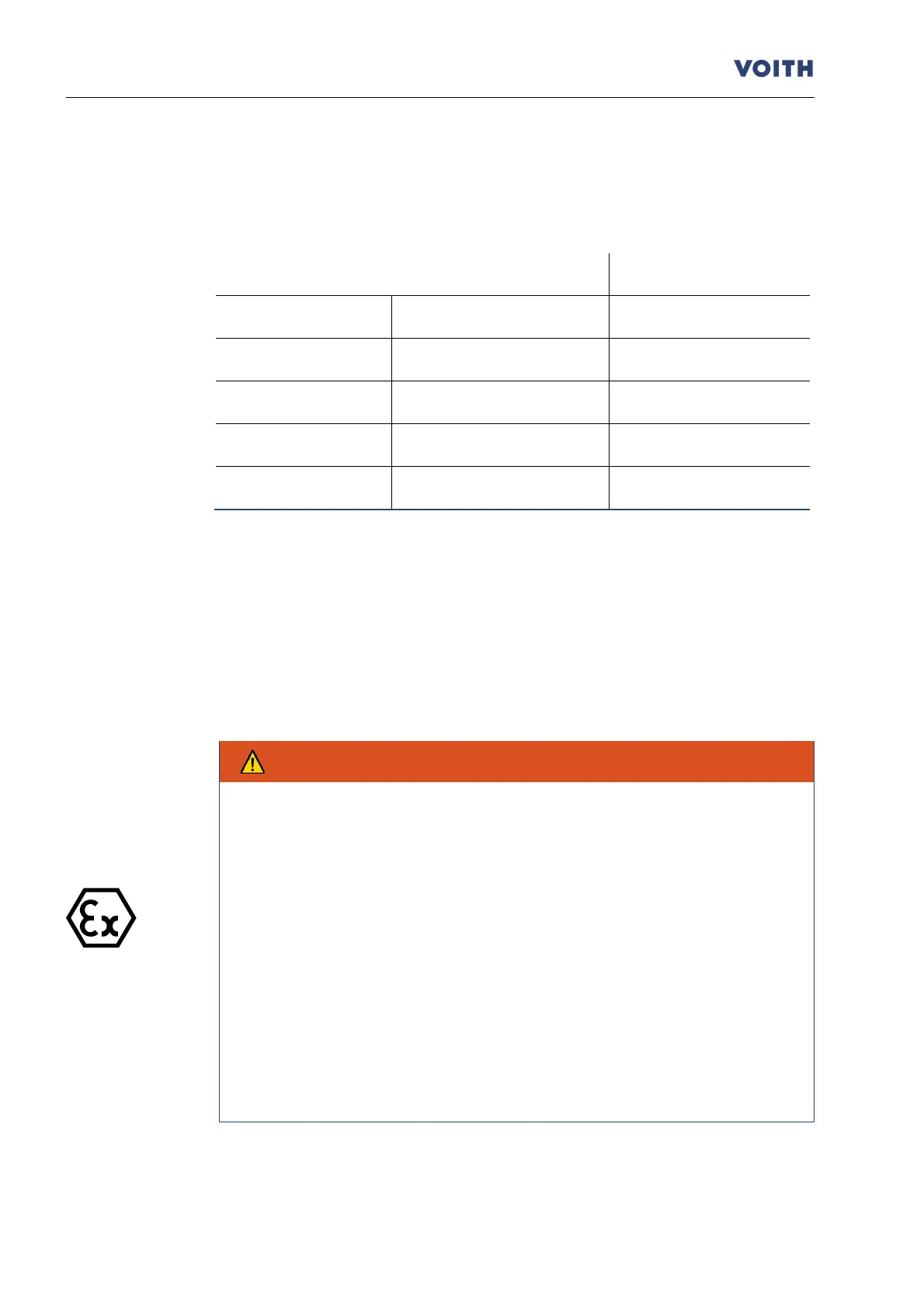
Standard combinations of switching elements and fusible plugs:
Nominal response temperatures
Table 4
The correlation between switching element and fusible plug may vary dependent on
the project design. Deviating nominal response temperatures of the switching element
(85 °C, 90 °C, 100 °C, 110 °C, 125 °C, 140 °C, 160 °C und 180 °C) are also available
( Chapter 13).
6.3 Mounting - switching element and initiator
-compliance with mounting instructions.
To avoid any damages, switching element and
initiator should be mounted
after installation and prior to filling the turbo coupling.
The switch unit and the connecting lines must not be damaged. Lay all lines
protected against mechanical impact.
It is not allowed to modify/change anything on
equipment which is operated in
potentially explosive atmospheres.
It is not possible to carry out repairs on such equipment.
Avoid any impact effects on the initiator. Work on the machine may only be
performed in non-hazardous atmospheres.
In order to pre
vent electrostatic charging, lay the connecting lines in
accordance with EN 60079-
14 and ensure that chafing during operation is not
possible.
•
Replace the blind screw by the switching element with the sealing ring in the turbo
coupling outer wheel (item 0300).
Voith Turbo
Ordering
documents