16
Fig.13
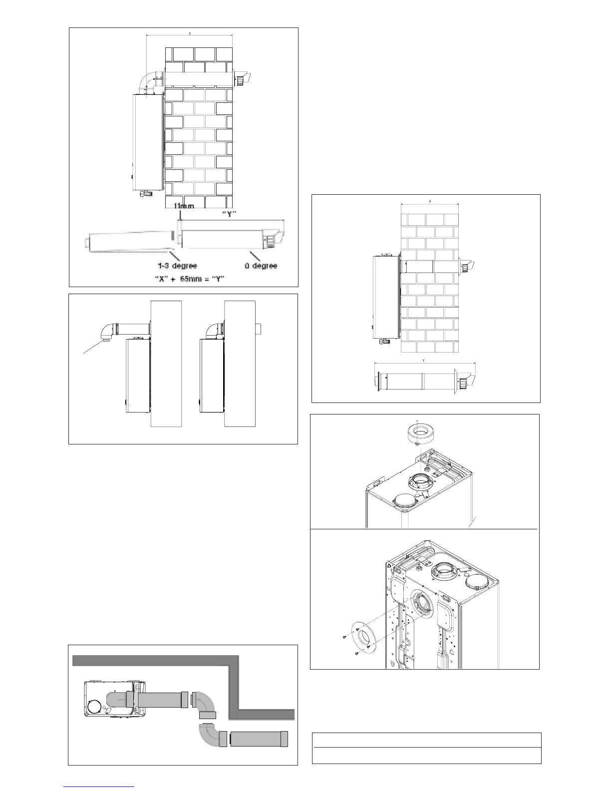
EXTENDING THE FLUE
Connect the bend – supplied with the terminal kit – to the top
taken to ensure that the correct seal is made when assembling
-
a minimum of 1º; maximum of 3º rise from the boiler to outside,
back to the appliance.
NOTE
When cutting an extension to the required length, you must
ensure that the excess is cut from the plain end of the extension
the wall using cement or a suitable alternative that will provide
Fig. 14
A
only)
Using the template provided, mark and drill a 125mm hole
mounting bracket should now be drilled and plugged, an ap-
that the bracket is mounted securely. Once the bracket has
telescopic terminal to the correct length (wall thickness) en-
suring that the terminal will protrude through the wall by the
correct distance. At this point, lift the appliance and carefully
insert the terminal into and through the wall, ensuring that the
holes in the appliance back frame are aligned with the studs
on the wall bracket.
Fig.15
Fig.17
Using the screws and washers provided, secure the appliance
onto the wall bracket and tighten with a suitable spanner.
Fig.16
Fig. 12
Part No. Description Length
29450133 825mm