EasyManua.ls Logo

VOKERA Vision C - Page 19

VOKERA Vision C
40 pages
Print Icon
To Next Page IconTo Next Page
To Previous Page IconTo Previous Page
Loading...
17
4.5.2 CONCENTRIC VERTICAL FLUE
The appliance can be used with either the Vokèra condensing


NOTE
These instructions relate only to the Vokèra condensing


to the instructions supplied.
-

      


Reduction for bends
 
45º bend 1.3 metre (60/100) - 1.0 metre (80/125)
90º bend 1.6 metre (60/100) - 1.5 metre (80/125)

Part No. Description Length
  
  
  
29450123 90-degree bend N/A
29450124 45-degree bends (pair) N/A
29450125 500mm extension 500mm
29450126 1000mm extension 1000mm
29450127 2000mm extension 2000mm
29450128 Telescopic extension 372/519mm
529 Wall bracket pack (5) 208mm

cut a 125mm hole in the ceiling and/or roof.
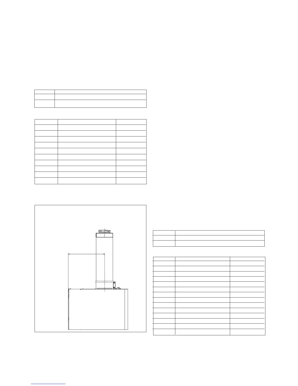
Fig. 18
“X”
12/15/20HE = 202mm
25/30/35HE = 218mm
130mm
-




should be used to ensure that the bracket is mounted securely.
Once the bracket has been secured to the wall, mount the ap-
pliance onto the bracket.
IMPORTANT

cut; therefore it may be necessary to adjust the height of the
appliance to suit or use a suitable extension.
-
ing the 100mm clip, gasket & screws (supplied), ensuring the


      




minimum 1º; maximum 3º fall back to the boiler (1º = 17mm
per 1000mm).
NOTE
When cutting an extension to the required length, you must
ensure that the excess is cut from the plain end of the exten-
sion. Remove any burrs, and check that any seals are located
properly.
-
ported and connected.
4.5.3 TWIN FLUE SYSTEM
      

used for horizontal or vertical applications, however the twin
        


instructions.
GUIDANCE NOTES ON TWIN FLUE INSTALLATION

17mm per 1000mm) fall back to the appliance to allow any

condensate drain. Consideration must also be given to the
fact that there is the possibility of a small amount of conden-
sate dripping from the terminal.

use at least one bracket for each extension.
-
res it must be protected to prevent persons touching the hot
surface.
-
ce with building regulations
Reduction for bends
 
45º bend 1.0 metre
90º bend 1.5 metre

Part No. Description Length
  
  
359 Twin adapter kit N/A
  
  
0225815 Condensate drain kit N/A
0225820 0.25m extension (pair) 250mm
0225825 0.5m extension (pair) 500mm
0225830 1.0m extension (pair) 1000mm
0225835 2.0m extension (pair) 2000mm
0225840 45º bend (pair) N/A
0225845 90º bend (pair) N/A
0225850 Twin bracket (5) N/A
0225855 Single bracket (5) N/A
MOUNTING THE BOILER


should be used to ensure that the bracket is mounted securely.
Once the bracket has been secured to the wall, mount the ap-
pliance onto the bracket.

Table of Contents

Related product manuals