18
NOTE
suitable alternative that will provide satisfactory weatherproof-
-
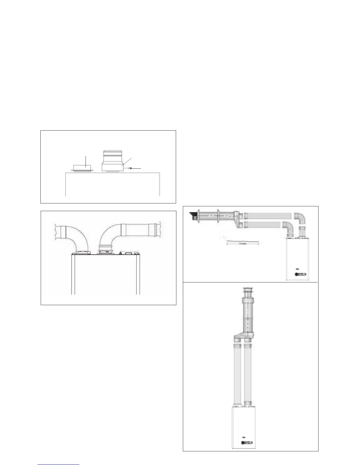
• The vertical terminal is supplied with a built-in converter box
and cannot be shortened.
• A 130mm hole is required for the passage of the concentric
terminal through the ceiling and/or roof.
Depending on site conditions it may be preferable to install the
-
ensuring that the exhaust pipe connects to the exhaust con-
nection on the concentric to twin converter.
allow connection to the concentric to twin converter.
NOTE
•
made for connection onto the previous piece and onto the
be pushed 50mm onto the male spigots of the concentric to
twin converter.
• -
ported and connected.
• Ensure that any horizontal sections of pipe have a fall
of between 1 & 3º towards the appliance (1º =17mm per
1000mm).
Fig. 21
Fig. 22
Fig. 19
-
• The horizontal terminal is supplied with a built-in converter
box and cannot be shortened.
• A 130mm hole is required for the passage of the concentric
terminal through the wall.
• The air inlet pipe must always be level with or below, that of
the exhaust pipe.
Depending on site conditions it may be preferable to install the
Mark and drill a level 130mm hole for the passage of the horizontal
box ensuring that the exhaust pipe connects to the exhaust
connection on the concentric to twin converter.
allow connection to the concentric to twin converter.
NOTE
made for connection onto the previous piece and onto the
pushed 50mm onto the male spigots of the concentric to twin
converter.
•
Insert the exhaust connection manifold (A) onto the appliance
• Remove the blanking plate (located to the left of the appliance
plate (B).
• Using the hole in the exhaust connection manifold as a guide,
provided (C).
• Using the two holes in the air inlet plate as a guide, drill a
3mm hole in each and secure the air inlet pipe/bend using
the screws provided.
installed by pushing together (the plain end of each extension
or bend should be pushed approximately 50mm into the female
socket of the previous piece).
B
A
C
Fig. 20
1-deg = 17mm