P
r
o
t
e
c
t
e
d
b
y
c
o
p
y
r
i
g
h
t
.
C
o
p
y
i
n
g
f
o
r
p
r
i
v
a
t
e
o
r
c
o
m
m
e
r
c
i
a
l
p
u
r
p
o
s
e
s
,
i
n
p
a
r
t
o
r
i
n
w
h
o
l
e
,
i
s
n
o
t
p
e
r
m
i
t
t
e
d
u
n
l
e
s
s
a
u
t
h
o
r
i
s
e
d
b
y
V
o
l
k
s
w
a
g
e
n
A
G
.
V
o
l
k
s
w
a
g
e
n
A
G
d
o
e
s
n
o
t
g
u
a
r
a
n
t
e
e
o
r
a
c
c
e
p
t
a
n
y
l
i
a
b
i
l
i
t
y
w
i
t
h
r
e
s
p
e
c
t
t
o
t
h
e
c
o
r
r
e
c
t
n
e
s
s
o
f
i
n
f
o
r
m
a
t
i
o
n
i
n
t
h
i
s
d
o
c
u
m
e
n
t
.
C
o
p
y
r
i
g
h
t
b
y
V
o
l
k
s
w
a
g
e
n
A
G
.
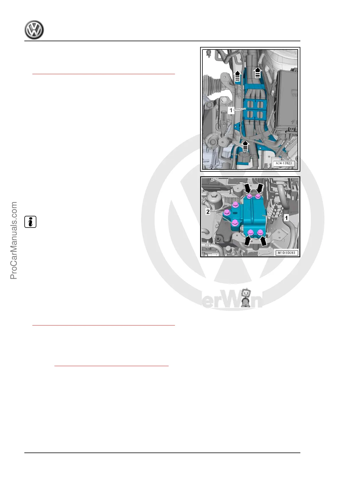
– Unclip the wiring guide -1- upward and move it slightly to the
side in direction of -arrows-.
– Support the engine in its installed position. Refer to
⇒ 2.5 Engine, Supporting in Installed Position, page 33 .
– Remove the bolts -2-, then the bolts -arrows- and remove the
transmission mount -1-.
Installing
Install in reverse order of removal. Note the following:
Note
♦
Replace the bolts which have been tightened to torque.
♦
The transmission support and the transmission mount support
arm must be absolutely parallel to each other before installing
bolts. Push the transmission up using a floor jack if necessary.
– Secure the transmission support to the longitudinal member.
– Pull the transmission up using the spindle on the engine sup‐
port bridge until the transmission support touches the trans‐
mission mount support arm.
– Install bolts by hand pay attention while doing so that the bolts
are not installed crooked.
– Check the adjustment of the assembly mounts. Refer to
⇒ 2.7 Subframe Mount, Checking Adjustment, page 37 .
– When the bolts are tightened to the tightening specification,
remove the Engine Support Bridge - 10-222A- from the en‐
gine.
Tightening Specifications
♦ Refer to ⇒ 2.1 Overview - Subframe Mount, page 29
♦ Refer to ⇒ Electrical Equipment; Rep. Gr. 27 ; Battery; Over‐
view - Battery .
Golf 2015 ➤ , Golf Variant 2015 ➤
Engine Mechanical, Fuel Injection and Ignition - Edition 04.2015
32 Rep. Gr.10 - Engine Assembly
ProCarManuals.com
 Loading...