P
r
o
t
e
c
t
e
d
b
y
c
o
p
y
r
i
g
h
t
.
C
o
p
y
i
n
g
f
o
r
p
r
i
v
a
t
e
o
r
c
o
m
m
e
r
c
i
a
l
p
u
r
p
o
s
e
s
,
i
n
p
a
r
t
o
r
i
n
w
h
o
l
e
,
i
s
n
o
t
p
e
r
m
i
t
t
e
d
u
n
l
e
s
s
a
u
t
h
o
r
i
s
e
d
b
y
V
o
l
k
s
w
a
g
e
n
A
G
.
V
o
l
k
s
w
a
g
e
n
A
G
d
o
e
s
n
o
t
g
u
a
r
a
n
t
e
e
o
r
a
c
c
e
p
t
a
n
y
l
i
a
b
i
l
i
t
y
w
i
t
h
r
e
s
p
e
c
t
t
o
t
h
e
c
o
r
r
e
c
t
n
e
s
s
o
f
i
n
f
o
r
m
a
t
i
o
n
i
n
t
h
i
s
d
o
c
u
m
e
n
t
.
C
o
p
y
r
i
g
h
t
b
y
V
o
l
k
s
w
a
g
e
n
A
G
.
5 Piston and Connecting Rod
⇒ 5.1 Overview - Piston and Connecting Rod, page 77 .
⇒ 5.2 Pistons, Removing and Installing, page 78 .
⇒ 5.3 Pistons and Cylinder Bore, Checking, page 80 .
⇒ 5.4 New Connecting Rod, Separating, page 84 .
⇒ 5.5 Connecting Rods, Checking Radial Clearance,
page 84 .
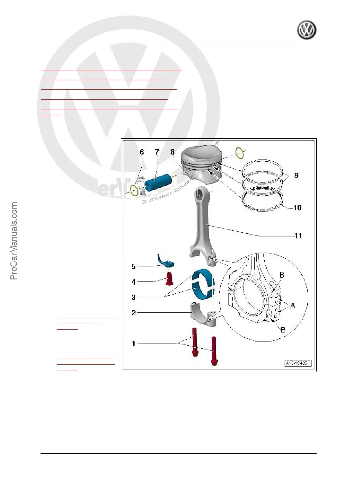
5.1 Overview - Piston and Connecting Rod
1 - Connecting Rod Bolts
❑ 45 Nm + 90°
❑ Use old bolt to measure
radial play
❑ Lubricate the thread and
contact surface.
❑ Replace after removing
2 - Connecting Rod Bearing
Cap
❑ Pay attention to the in‐
stalled position.
❑ Due to the separation
procedure (cracking) of
the connecting rod, the
connecting rod bearing
cap only fits in one posi‐
tion and only to the cor‐
responding connecting
rod.
❑ Mark affiliation to cylin‐
der -A-
❑ Installed position: the
markings -B- face the
belt pulley side
❑ Disconnect the new
connecting rod. Refer to
⇒ 5.4 New Connecting
Rod, Separating,
page 84 .
3 - Bearing Shells
❑ Installed position. Refer
to
⇒ Fig. Installed Posi‐
tion of Bearing Shell ,
page 78
❑ Do not interchange used bearing shells (mark)
❑ Coat with oil before installing
❑ Axial play new: 0.10 to 0.35 mm, wear limit: 0.40 mm
❑
Check radial clearance with Plastigage
®
, new: 0.02 to 0.06 mm, wear limit: 0.09 mm. Do not turn crank‐
shaft when checking radial clearance
4 - Relief Valve
❑ 27 Nm
5 - Oil Spray Jet
❑ For piston cooling
Golf 2015 ➤ , Golf Variant 2015 ➤
Engine Mechanical, Fuel Injection and Ignition - Edition 04.2015
5. Piston and Connecting Rod 77
ProCarManuals.com
 Loading...