P
r
o
t
e
c
t
e
d
b
y
c
o
p
y
r
i
g
h
t
.
C
o
p
y
i
n
g
f
o
r
p
r
i
v
a
t
e
o
r
c
o
m
m
e
r
c
i
a
l
p
u
r
p
o
s
e
s
,
i
n
p
a
r
t
o
r
i
n
w
h
o
l
e
,
i
s
n
o
t
p
e
r
m
i
t
t
e
d
u
n
l
e
s
s
a
u
t
h
o
r
i
s
e
d
b
y
V
o
l
k
s
w
a
g
e
n
A
G
.
V
o
l
k
s
w
a
g
e
n
A
G
d
o
e
s
n
o
t
g
u
a
r
a
n
t
e
e
o
r
a
c
c
e
p
t
a
n
y
l
i
a
b
i
l
i
t
y
w
i
t
h
r
e
s
p
e
c
t
t
o
t
h
e
c
o
r
r
e
c
t
n
e
s
s
o
f
i
n
f
o
r
m
a
t
i
o
n
i
n
t
h
i
s
d
o
c
u
m
e
n
t
.
C
o
p
y
r
i
g
h
t
b
y
V
o
l
k
s
w
a
g
e
n
A
G
.
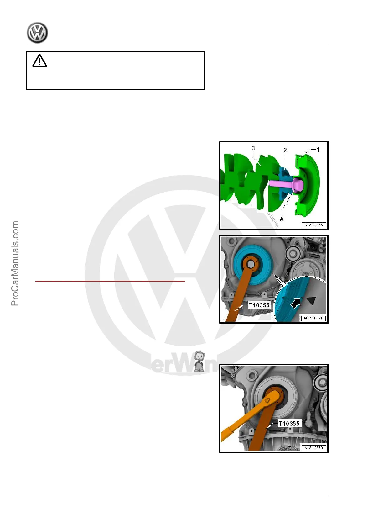
Caution
This procedure contains mandatory replaceable parts. Refer
to component overview prior to starting procedure.
Mandatory Replacement Parts
♦ Bolts - Timing Chain Cover
♦ Bolt - Vibration Damper
♦ O-ring - Vibration Damper
The vibration damper bolt -A- connects the vibration damper -1-
timing chain connection -2- and the crankshaft -3-. Secure the
chain sprocket as described as follows to the crankshaft, before
removing the vibration damper.
Remove Vibration Damper
– Remove the right wheel housing liner front section. Refer to ⇒
Body Exterior; Rep. Gr. 66 ; Wheel Housing Liner; Front
Wheel Housing Liner, Removing and Installing .
– Remove the ribbed belt. Refer to
⇒ 1.2 Ribbed Belt, Removing and Installing, page 46 .
– Remove the Locking Pin - T10060A- from the ribbed belt ten‐
sioner.
– Turn the vibration damper with the Counterhold - Vibration
Damper - T10355- to the Top Dead Center (TDC) point
-arrow-.
• The notch on the vibration damper must line up with the arrow
marking on the timing chain lower cover.
• The marking for the cover is located in the »four-o'clock posi‐
tion«.
–
Loosen the vibration damper bolt approximately
1
/
2
turn, to do
this use the Counterhold - Vibration Damper - T10355- .
– If the vibration damper was turned, correct to TDC.
Golf 2015 ➤ , Golf Variant 2015 ➤
Engine Mechanical, Fuel Injection and Ignition - Edition 04.2015
48 Rep. Gr.13 - Crankshaft, Cylinder Block
ProCarManuals.com
 Loading...