General Information about the ECM
7.4 Gi models
The funcbon of the fuel metering system is to deliver
the correct amount of fuel to the engine under all op-
erating condtlons Fuel is dehvered by eight fuet
injectors controlled by the Engine Control Module
(ECM)
The ECM looks at voltage from several sensors to
determine how much fuel to give the engine.
One of the sensors is the Mamfold Absolute Pres-
sure Sensor (MAP) that measures the pressure in the
intake manifold. The MAP sensor allows the ECM to
automatically adjust for d~fferent aEtitudes. No
high altitude adjustment is necessary.
The Knock Sensor detects abnormal engine wbra-
tions (spark knock) The ECM uses the knock sen=
sor voltage to calculate the tgnitlon tlmng
A
WARNING! It Is extremely important that the
correct Knock Sensor is used The Knock
sensor ~s un=qe for th~s marine engine Never
subsbtute wrth automot[ve or other sensors
as this can result in engine damage If the
Knock Sensor has been removed ~t must be
installed correctly. Be sure the threads are
clean and bghten to 11-16 lb ft. (15-22 Nm)
the Knock Sensor is over or under torqued it
will give false signals Consult your Volvo
Penta dealer for asststence.
The electronics m the ECM are protected m sever
at ways for false signals and interference The fol-
lowing should be observed; Never mount radl-
otransmRter antennas near the ECM unit, or
ground any wiring to the engine Do not wtre send-
er antenna cables near the ECM as electromag-
netic fields can dzsturb the ECM electronics
If the engine floods it can be cleared by opening
the throttle to 75% of its travel The ECM then
shuts down the fuel rejectors so no fuel is delivered
as long the throttle stays at 75% and the engine
speed speed is below 400 rpm (cranking speed)
throttle poslbon becomes greater or less than 75%
the ECM returns to the starting mode
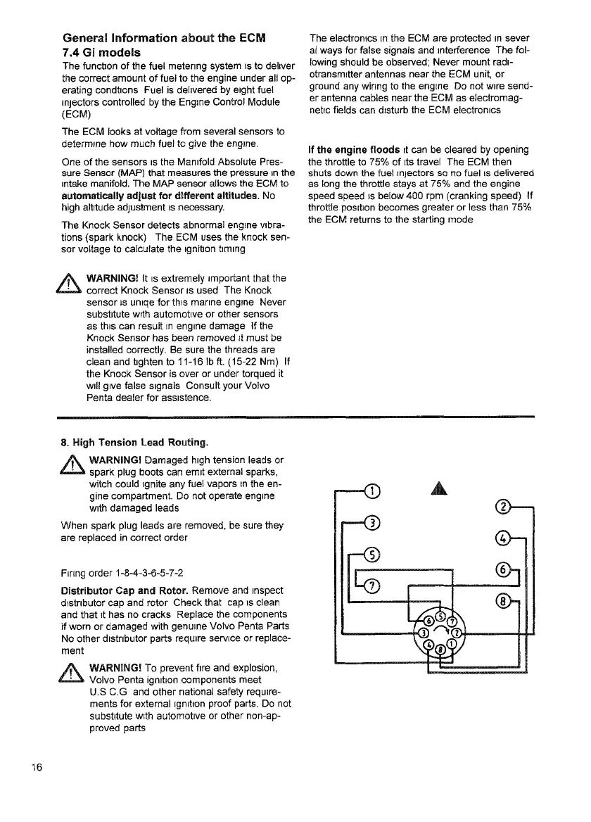
8. High Tension Lead Routing.
~
WARNING! Damaged high tension leads or
spark plug boots can emit external sparks,
witch could tgnite any fuel vapors ~n the en-
gine compartment. Do not operate engine
with damaged leads
When spark plug leads are removed, be sure they
are replaced in correct order
Fmng order 1-8-4-3-6-5=7-2
Distributor Cap and Rotor. Remove and respect
distnbutor cap and rotor Check that cap ~s clean
and that it has no cracks Replace the components
if worn or damaged with genuine Volvo Penta Parts
No other dlstnbutor parts require serv{ca or replace-
ment
A
WARNING! To prevent fire and explosion,
Volvo Penta igmtJon components meet
U.S C.G and other national safety requtre-
ments for external Egnltlon proof parts. Do not
substitute with automottve or other non-ap-
proved parts
16
7788827 - Ladattu osoitteesta www.volvopenta.com 17.11.2010 12:21:31