68
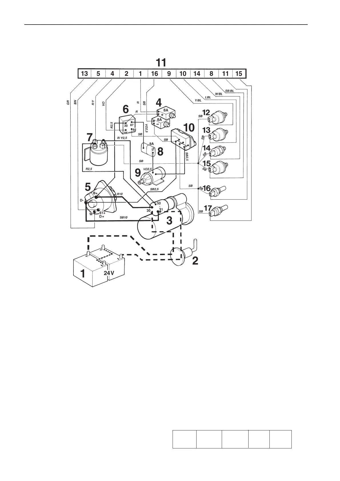
TAMD162C*, engine (non-classifiable engine specification)
* Applies up to and incl. engine No. 1101052586/xxxx.
1. Battery
2. Main switch
3. Starter motor
4. Semi-automatic fuses (8A)*
5. Generator (GEN)
6. Stop relay (16S)*
7. Start relay (16MS)
8. Ceramic 8A fuse for stop solenoid*
9. Stop solenoid
10. Ground terminal block*
11. Connector, 16-pin*
12. Turbo pressure sender (accessory)
13. Oil pressure sender, engine
14. Oil pressure switch, engine
15. Oil pressure sender, reverse gear (accessory)
16. Engine coolant temp. (ECT) sender (40 – 120
o
C)
17. Engine coolant temperature (ECT) switch (97°C/207°F),
(normally open – closes if fault occurs)
* Located in terminal box.
Cable color
BL =Blue R =Red
LBL = Light-blue SB = Black
BN = Brown VO = Violet
LBN = Light-brown W = White
GR = Gray Y = Yellow
Cable areas in mm
2
are noted after the color codes
in the wiring diagrams.
If no cable area is stated the default is 1.0 mm
2
Conversions mm
2
/AWG*
* American Wiring Gauge
mm
2
0.75 1.5 4 16
AWG 18 15 (16) 11 5