89
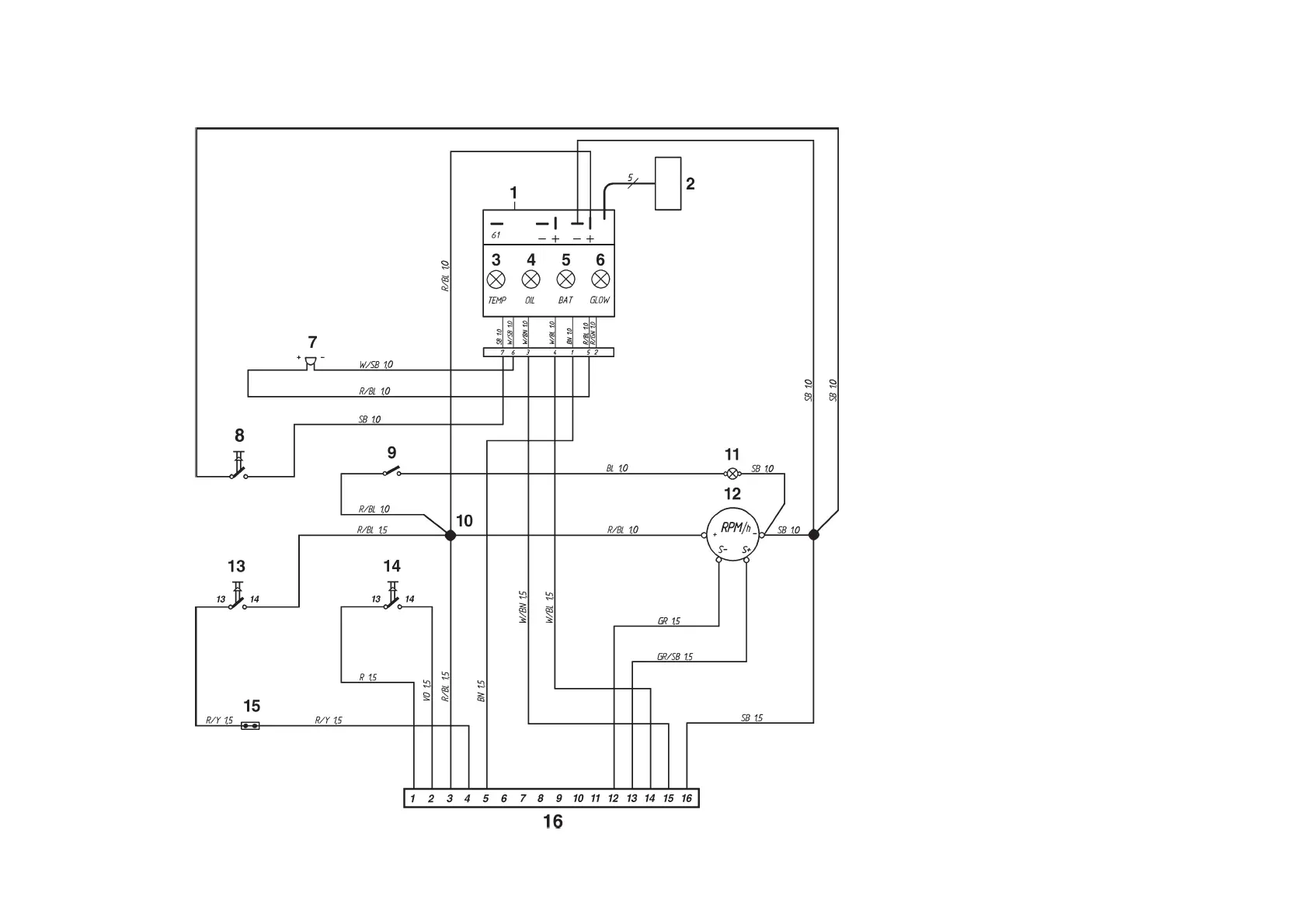
Flying Bridge instrument kit
1. Electronics module (alarm)
2. Connector for extra warning display
(accessory)
3. Engine coolant temperature warning lamp
4. Oil pressure warning lamp
5. Charge warning lamp
6. Control lamp, pre-heating (TAMD71B)
7. Alarm
8. Alarm test/acknowledgement switch
9. Switch, instrument panel lighting
10. Connector (cannot be opened)
11. Instrument lighting
12. Tachometer with built-in hours run meter
13. Starter button
14. Stop button
15. Connector for connecting neutral position
switch, if fitted (accessory)
16. 16-pin connector
Cable color
BL = Blue
LBL = Light-blue
BN = Brown
LBN = Light-brown
GN = Green
GR = Gray
OR = Orange
P = Pink
R = Red
SB = Black
VO = Violet
W = White
Y = Yellow
Cable areas in mm
2
are given after the
color codes in the wiring diagrams.
7740156 - Downloaded from www.volvopenta.com 22/07/2009 00:44:08
 Loading...