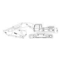
To deactivate the trailer lifting function move the control lever
back to neutral position and press the button (5) again.
N
T
E
!
If the double acting trailer lifting option is engaged (trailer lift ing
activation switch (10) in upper end position) it is not possible to
move the stabiliser legs / stabiliser blade.
Disengage the double acting trailer lifting option by pressing the
trailer lifting activation switch (10) to the lower end position.
i
h
h
e
n
l
e
c
i
t
i
n
the left control lever is only tilting
up the loading platform, tilting back is done by pressing the
lower end of the trailer lifting activation switch (10).
New function added only for models with serial number start:
EW160E 322329; EW7R180E 322114.
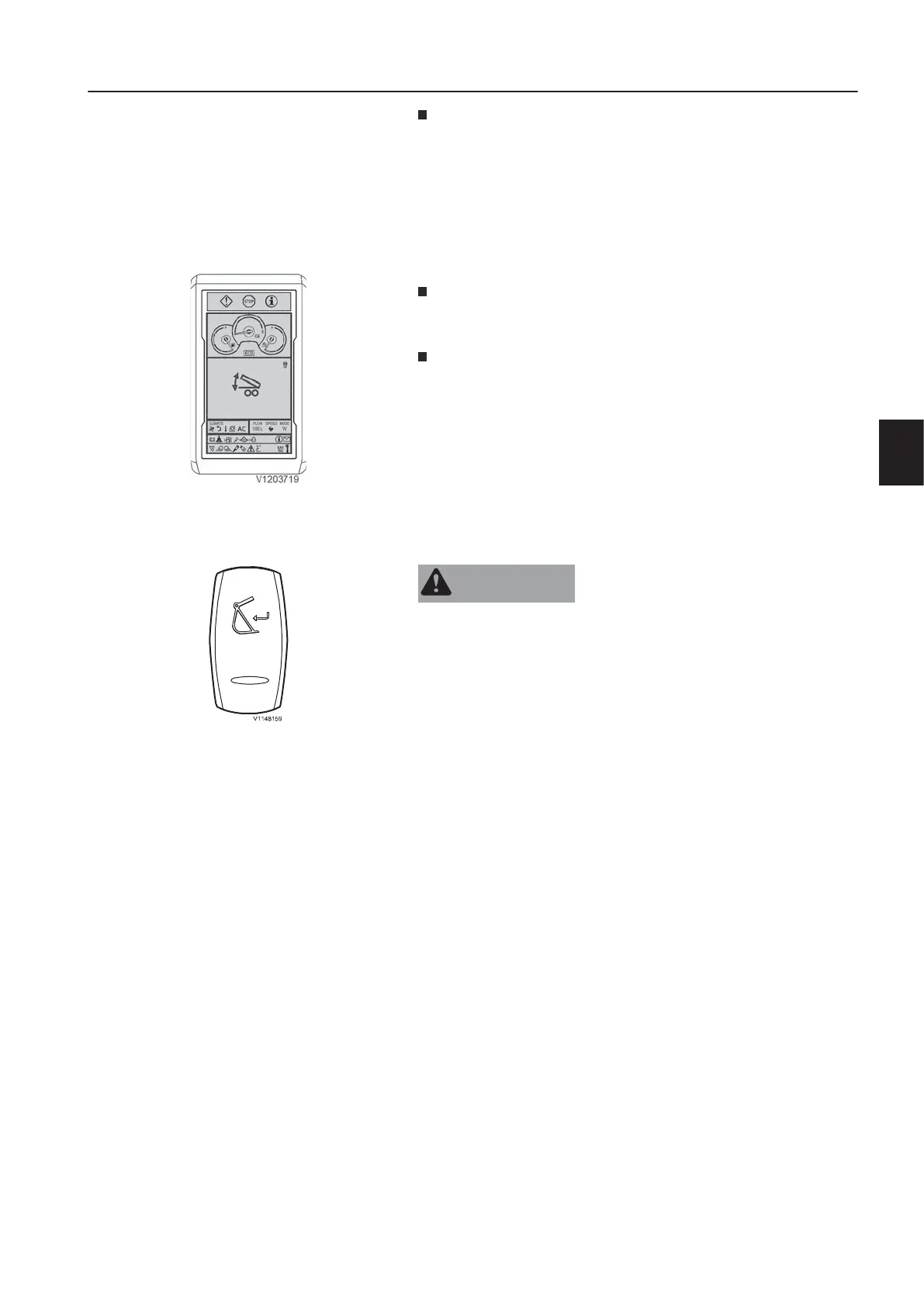
If both, the trailer switch and the function joystick controlled
support are activated, a popup of the trailer symbol is shown in
the display instead of the stabilizer menu.
For all other control lever functions see page
94
.
8
.
t
t
a
c
m
e
n
t
u
i
c
u
p
l
e
r
n
f
i
r
m
a
t
i
o
n
i
t
c
A
R
N
I
N
G
Risk of crushing!
Attachments that move unexpectedly can cause injuries.
k
r
e
p
l
e
a
f
h
e
r
n
a
n
n
i
r
n
n
c
i
t
a
c
m
s
T
E
!
The attachment quick coupler switch (position 11) on the right
instrument panel must be pressed to initiate the opening of the
attachment quick coupler. The buzzer sounds continuously after
this switch is pressed. See page
80
for the operation.
O
p
e
i
n
g
f
h
e
t
a
c
m
n
u
p
l
e
r
Press down and hold the upper end of the spring returned quick
coupler confirmation switch on the left instrument panel for 1
second.
A red quick coupler symbol and a warning message for unlocked
quick coupler will appear in the IC (Instrument Cluster).
Connect the attachment according to the operation description on
page
210
.
N
T
E
!
The attachment quick coupler switch (position 11) on the right
instrument panel must be deactivated afterwards to initiate the
closing of the attachment quick coupler. See page
80
for the
operation.
C
n
f
i
s
n
g
f
h
e
t
t
a
n
t
u
c
r
After checking the correct locking of the attachment in the
attachment quick coupler this has to be confirmed by pressing the
upper end of the attachment quick coupler confirmation switch for
1 second.
A yellow quick coupler symbol and a check message for quick
coupler locking confirmation will disappear in the IC (Instrument
Cluster) and the buzzer sound will stop.
e
a
0
f
o
r
h
m
e
t
e
c
d
u
r
h
e
t
a
c
m
u
i
c
u
p
l
e
r
r
i
o
.
Trailer symbol visible when activated
n
s
r
u
m
e
n
t
a
n
e
l
s
n
s
r
u
m
e
n
t
a
n
e
l
,
e
f
t
7