Controls
Hydraulic controls 65
n Push forward on the lever for the side you wish to lower.
n Pull back on the lever for the side you wish to raise.
Electric float valves
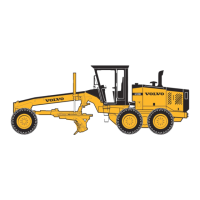
n On graders equipped with optional blade float, push forward
on the lever until it locks in the detent (see figure). Pull back-
ward on the lever to return it to the normal operating position.
Front float valve system operation
Graders equipped with float valves allow the moldboard and/or A-
frame attachment to ‘float’ along the ground by following the sur-
face contours. For snow wing float, refer to Hydraulic snow wing
page 121.
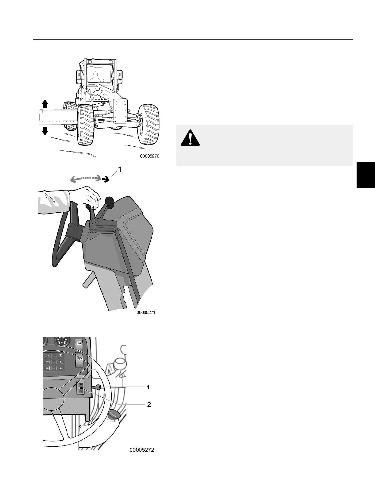
Either or both blade lift cylinders can be put into float to allow in-
dependent control of each end of the moldboard.
Use moldboard float to remove snow, move loose material on
hard-packed surfaces or to level loose material to a hard surface.
(Float only the moldboard end contacting the hard surface.)
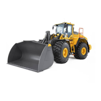
n The float valves power switch is located on the right-hand side
of the pedestal.
n Ensure the levers are in the non-float detent position.
n Push the power switch up to activate the system. This is a mo-
mentary style switch. Indicator lamps mounted on the front
right-hand side of the pedestal indicate that the system is ac-
tivated.
n The ignition key must be in the “I” position to activate the sys-
tem using the float valves power switch.
n Push the float valves power switch down to de-activate the
system. The system also de-activates when you turn the igni-
tion key to the OFF position.
WARNING!
Do not use the float control to lower the moldboard. Loss
of control of the grader could result.
1 Float detent position
1 Float valves power switch
2 Front float valve system indicator lamps



 To Next Page