EasyManua.ls Logo

Von Duprin 98 User Manual

Von Duprin 98
9 pages
To Next Page IconTo Next Page
Page #1 background imageLoading...
Page #1 background image
FAX version 911373_00(1) Page 1 of 9
Installation Instructions
®
98/99 Series Rim Exit Device
This product is covered by the
following patent numbers:
3,767,238 4,427,223
3,854,763 4,466,643
4,167,280 4,741,563
911373_00(1) Copyright © 2002 Ingersoll-Rand Company. All rights reserved.
Devices covered by these instructions:
98/99 Rim Exit Device
98/99-F (Fire) Rim Exit Device
CD98/CD99 (Cylinder Dogging) Rim Exit Device
98-2/99-2 (Double Cylinder) Rim Exit Device
EL98/EL99 (Electric Latch Retraction) Rim Exit Device
Index:
Screw chart ................................... 2
Preparation chart ......................... 3
Device installation ...................4-6
Optional equipment ................7-8
Cut device ..................................... 9
499F strike installation ............... 9
Special tools needed:
5/64 hex wrench
#10-24 tap
5/8 spade drill (99-F wood door)
Drill bits: #25, 1/8, 1/4,
5/16, 3/8, 13/32
VON DUPRIN
®
Question and Answer IconNeed help?

Do you have a question about the Von Duprin 98 and is the answer not in the manual?

Von Duprin 98 Specifications

General IconGeneral
Device TypeExit Device
Fire RatedYes
HandingUniversal
Finish OptionsUS10B, US26D
Minimum Door Width24 inches
Maximum Door Width48 inches
FastenersIncluded
ANSI StandardANSI A156.3 - Grade 1
TypeExit Device
FunctionExit
MaterialSteel
ComplianceANSI
Backset2-3/4 inches

Summary

Von Duprin 98/99 Series Installation

Product Overview and Required Tools

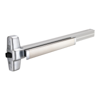
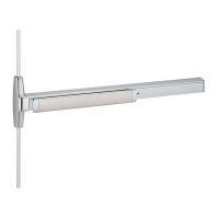
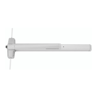
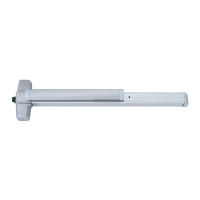
Details the specific exit device models covered and lists necessary special tools for installation.

Screw Chart Details

Screw Applications and Types

Categorizes screws by their application and type (e.g., metal frame, wood frame, sex bolts) for installation.

Preparation Chart and Door Cut-outs

End Cap Bracket and Center Case Preparation

Details drilling and tapping requirements for end cap brackets and center cases for various door types.

Specific Cut-out for 99-2 Double Cylinder

Provides detailed dimensions and instructions for cutting out the door for the 99-2 double cylinder option.

Installation Steps: Marking and Drilling

Step 1 & 2: Center Lines and Strike Alignment

Outlines steps for drawing center lines and aligning the strike for the exit device installation.

Step 3 & 4: Hole Preparation and Marking

Details preparing holes for the strike and marking the door using a template.

Installation Steps: Device Mounting

Lock Side Prep and Trim Installation

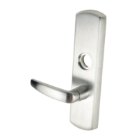
Covers preparing the lock side of the door and installing the trim if applicable.

Mounting Bracket and End Cap Securing

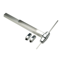
Instructions for installing the mounting bracket and end cap for the exit device.

Final Installation Steps

Support Screws and Center Case Cover

Guides on installing support screws and the center case cover.

Strike Adjustment and Securing

Details how to adjust and secure the strike plate, including shimming if necessary.

Optional Equipment: Cylinder Dogging

CD Function Conversion and Operation

Explains the process of converting the device for cylinder dogging and how to operate it using a key.

Optional Equipment: Double Cylinder

99-2 Cylinder Bracket Assembly

Details how to assemble and mount the rim cylinder to the cylinder bracket and center case.

Optional Equipment: EL Wiring and Adjustment

EL Solenoid Wiring and Specifications

Provides electrical specifications for the solenoid and notes on wiring and operation.

Solenoid Operation and Troubleshooting

Offers guidance on troubleshooting issues with the solenoid's latch bolt retraction and holding functions.

Dogging Rod Adjustment Procedure

Instructions on adjusting the dogging rod to ensure proper latch bolt operation for retraction and extension.

Cut Device and Strike Installation

Device Cutting and Anti-Rattle Clip

Outlines the steps for measuring, marking, and cutting the exit device and installing the anti-rattle clip.

499F Strike Installation Steps

Guides on preparing screws, installing the strike hook, and aligning the template for the 499F strike.

Related product manuals