VA41620/VA41630 Evaluation Board User’s Manual
V1.0
7
tied together. Additional jumpers placed on JP8 can configure a different clock frequency for
the MCU as follows.
Table 2 - PEB1 MCU Board Connector designations for clock selection
1.6 Materials List
• PEB1 evaluation boards – Programmed with demonstration program
• 36” Micro USB cable
• Insert card with component placement picture and URL
• 10 jumpers and several wires
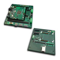
1.7 Board connectivity
This photo shows the PEB1 MCU board mounted onto the PEB1 GPIO board. The connection
between these two boards is made by aligning the plastic pins on the lower board with the
holes on the upper board. Similar connectivity is achieved with the PEB1 MCU board and the
PEB1 EBI/Ethernet board.