VA41620/VA41630 Evaluation Board User’s Manual
V1.0
17
• VA416x0 Software Development kit (Folder structure with many *.c, *.h and
Project files)
• VA416x0 Software Documentation (html file structure)
• VA416x0 Pack file with programming algorithms, header and .SVD files. (Single
.zip file that can either be open separately or by the Keil IDE)
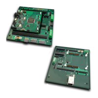
• PEB1 Schematic (Three .pdf documents)
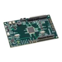
o PEB1 MCU board
o PEB1 GPIO board
o PEB1 EBI/Ethernet board
• PEB1 User’s Manual (Single .pdf document)
• PEB1 Quick Start Guide (Single .pdf document)
3 Hardware check
3.1 Powering up the board
The Segger J-Link driver needs to be loaded prior to plugging the board to a PC. See 2.1.2.
• Before connecting the board conduct a jumper check. Only the following jumpers
should be inserted:
o 5v supply from USB jumper on JP10
o Clock source JP8. Jumper between pins 7 and 8.
o MCU voltage 3.3v and 1.5v supply shunts on JP4 (pin 5 to 6 and pin 7 to 8)
o Analog voltage supply connections on JP15 (all four jumpers in place)
• Connect the USB cable between PC and the PEB1 board
o The green DS1 LED will indicate that power is applied to the board.
• If the MCU has the pre-programmed example code running, the green LED DS2 will blink
to show that the code is running.
o Pressing the RESET button (SW1) will hold the device in RESET. Releasing it will
commence the boot sequence and start code executing.
4 Command line control of the EVK
By using “PuTTY” or “Tera Term”, terminal window interface applications, it is possible enter
commands and monitor the outputs in a log file or terminal window.
The following table contains all the supported commands that the firmware will recognize.