Do you have a question about the VWR International 1327F and is the answer not in the manual?
Inspect for visible exterior damage upon delivery and note damage on the freight bill. Enter claim with the carrier.
Inspect for concealed loss or damage on the unit's interior and exterior. Carrier will arrange official inspection for claims.
Save shipping carton. Contact customer service for authorization and provide data plate information for returns.
Verify all equipment indicated on the packing slip is included. Check packaging before discarding for 2 shelves, 8 shelf clips, thermometer.
Symbol indicates consulting the manual for further description or discussion of a control or user item.
Indicates AC Power.
Indicates Adjustable Temperature.
Indicates Manual Control.
Indicates Heating.
Indicates Over Temperature.
Indicates Protective Earth Ground.
Indicates Potential Shock Hazard.
Indicates the unit should be recycled and not disposed of in landfill.
Ensure power source matches data plate voltage, cycle, phase, and ampere requirements. Voltage should not vary by more than 10%.
Select an indoor location considering temperature, humidity, and airflow. Allow at least 10cm clearance from walls.
Use appropriate lifting devices. Lift from bottom surfaces only. Restrain unit from tipping during transport.
Unit must sit level and solidly. Use non-adjustable rubber feet. Ensure the counter surface is level.
Remove interior parts. Clean chamber thoroughly with an appropriate disinfectant and rinse with a damp cloth.
Place shelves in the chamber at the desired position using the provided shelf clips. Ensure clips are installed at the same elevation.
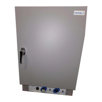
The main power I/O switch controls all power to the oven. Must be in the ON position for systems to be operational.
Sets the oven temperature using an adjustment knob and graduated dial with 10 major increments.
Green pilot light indicates when the heating element is activated and the oven is heating.
Independent control for safety temperature protection. Limits rise to approx. 10°C above the main set point.
Red pilot light indicates when the Over Temperature Thermostat has activated. Should not be on during normal operation.
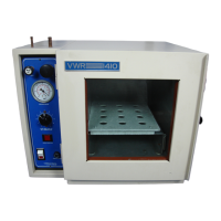
The exhaust damper should be open during drying or degassing for best results.
This oven is NOT explosion proof and is not designed to handle combustible gases. Do not place flammable materials inside.
Ventilate exhausts to the outside if byproducts are hazardous or unpleasant, following local regulations.
Do not place sealed or filled containers in the oven chamber to prevent pressure buildup.
This oven is NOT designed for use in Class I, II, or III locations as defined by the National Electrical Code.
This oven is not intended or approved for use as a patient connected device.
Ensure power supply is properly grounded and sized. Match voltage to data plate (within 10%). Connect cord set securely.
Push power switch to ON. Turn Over Temperature Thermostat to maximum position.
Place reference thermometer through the exhaust port on top of the unit using the provided clip.
Set Main Temperature Controller knob to desired value. Allow one hour for stabilization and adjust as needed using reference thermometer.
Set Over Temperature Thermostat to approx. 10°C above Main Temperature set point by adjusting knob until light goes off.
Clean oven interior regularly with appropriate disinfectant. Rinse with damp cloth. Avoid chlorine bleaches and abrasive cleaners.
For extended shut down, clean and dry the chamber. Remove shelving and trays, lock door, and disconnect power for transport.
No maintenance is required on electrical components. Refer to Troubleshooting for operational failures.
Check controller setting, controller failure, or wiring error. Contact customer service if controller failed or wiring is suspect.
Recalibrate the unit by adjusting the thermostat and controller settings as described in sections 6.3 and 6.4.
Check thermostat, controller settings, unit recovery, element failure, or wiring. Verify pilot light indicates heating.
Confirm amperage/voltage, set point high enough, sensor connections, and calibration. Adjust thermostat clockwise.
Verify heating indicator light, check amperage, thermostat setting, and fuses/breakers. Contact customer service for controller issues.
Check ambient conditions, exhaust stack, calibration sensitivity, or thermostat setting. Contact customer service for sensitivity issues.
Assure set point is at least 5 degrees over ambient. Check ambient fluctuations or thermostat setting. Adjust as per section 6.5.
Confirm that the door gasket is aligned properly and that the unit body is square and undamaged.
Check wall power source, compare current draw to data plate, and check other loads on the wall circuit.
Check wall power source, unit fuse/breaker, and wiring connections, especially around the on/off switch.
Place unit under vent and run at full power for one hour to burn off manufacturing residues.
Refer to cleaning procedures in section 7.1. Develop SOP for specific applications, including cleaning and maintenance.
Lists descriptions, part numbers for 115V and 220V, including controls, heating elements, and accessories.
Provides shipping and net weight, exterior and interior dimensions for models 1310 and 1320.
Details cubic feet capacity, temperature range, and uniformity for models 1310 and 1320.
Lists descriptions, part numbers for 115V and 220V, including controls, heating elements, and accessories.
Provides shipping and net weight, exterior and interior dimensions for models 1324 and 1325F.
Details cubic feet capacity, temperature range, and uniformity for models 1324 and 1325F.
Lists descriptions, part numbers for 115V and 220V, including controls, heating elements, and accessories.
Provides shipping and net weight, exterior and interior dimensions for models 1326 and 1327F.
Details cubic feet capacity, temperature range, and uniformity for models 1326 and 1327F.
Illustrates NEMA 5-15P and NEMA 6-15P plug styles for domestic units.
Illustrates CE model inlet plugs, filters, and IEC 320 inlet for European market units.
Shows the wiring connections for ON/OFF switch, regulating control, safety control, and heating element.
Illustrates NEMA 5-15P and NEMA 6-15P plug styles for domestic units.
Illustrates CE model inlet plugs, filters, and IEC 320 inlet for European market units.
Shows the wiring connections for ON/OFF switch, regulating control, safety control, and heating element.
Diagram shows circuit breaker and ON/OFF switch connections for the unit.
Illustrates wiring for rotisserie ON/OFF switch, gear motor, and speed adjustment.
Shows connections for the digital display, temperature controller, thermal limit, and heating element.
Diagram shows the wiring for the chamber blower motor.
Two-year warranty for defects in material and workmanship. Covers repair, replacement, or refund at manufacturer's election.
Excludes labor charges outside U.S.A., damage from misuse, negligence, or alterations. Void if serial number is removed.
Disclaims all other warranties, express or implied, including merchantability and fitness for a particular purpose.
Provide Model, Serial No., and Part No. for fast and efficient support requests.
| Temperature Stability | ±0.5°C |
|---|---|
| Shelves | 2 |
| Voltage | 120V |
| Frequency | 50/60 Hz |
| Controller Type | Digital |
| Material | Stainless steel |
| Weight | 60 lbs (27 kg) |