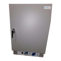
EasyManua.ls Logo

VWR International 1330FM User Manual

Default Icon
25 pages
To Next Page IconTo Next Page
Page #1 background imageLoading...
Page #1 background image
MICROPROCESSOR
CONTROLLED OVENS
M
ODELS: 1330FM,1350FM,1370FM
1330GM,1350GM,1370GM
1330FMS,1350FMS,1370FMS
1330GMS,1350GMS,1370GMS
INSTALLATION AND OPERATION MANUAL
Sheldon Manufacturing Inc. P.O. Box 627 Cornelius, Oregon 97113
EMAIL: tech@Shellab.com
INTERNET: http://www.Shellab.com/~Shellab
1-800-322-4897 (503) 640-3000 FAX (503) 640-1366
Question and Answer IconNeed help?

Do you have a question about the VWR International 1330FM and is the answer not in the manual?

VWR International 1330FM Specifications

General IconGeneral
BrandVWR International
Model1330FM
CategoryOven
LanguageEnglish

Summary

Receiving and Inspection

Inspection

Inspect for visible exterior damage upon delivery and document any findings on the freight bill.

Concealed Loss or Damage Inspection

Inspect the unit's interior and exterior for hidden damage after delivery.

Accessories Verification

Confirm that all included accessories, such as leveling feet and shelves, are present.

Return Shipment Procedure

Follow authorization procedures and include serial number for unit returns.

Graphic Symbols

Consult Manual Symbol

Indicates that the user should refer to the manual for further details on a control or item.

AC Power Symbol

Symbol indicating the presence of AC power.

Manual Control Symbol

Symbol denoting manual control operation.

Timer Symbol

Symbol representing the timer function.

Degrees Celsius Symbol

Symbol for temperature measurement in degrees Celsius.

Temperature Symbol

Symbol indicating temperature measurement.

Over Temperature Safety Symbol

Symbol for the over-temperature safety feature.

Earth Ground Symbol

Symbol indicating an earth ground connection for safety.

Potential Shock Hazard Symbol

Warning symbol indicating a potential electrical shock hazard.

Recycle Symbol

Symbol indicating the unit should be recycled and not disposed of in landfills.

Installation

Power Requirements

Verify that the unit's power supply matches the data plate specifications for voltage and frequency.

Location Selection

Choose a suitable location free from extreme temperatures and with adequate airflow space.

Lifting and Handling Procedures

Use appropriate lifting devices and ensure the unit is secured to prevent tipping during movement.

Leveling the Unit

Ensure the unit sits level and solidly using the adjustable leveling feet.

Interior Cleaning

Clean the interior chamber with a suitable disinfectant before first use.

Initial Burn-In Process

Run the oven at 200°C for one hour with ventilation to burn off protective coatings.

Precautions

Work Surface Restriction

The bottom surface of the chamber should not be used as a work surface.

Chamber Ventilation and Gas Handling

Ensure proper ventilation, especially when handling hazardous or unpleasant out-gassed by-products.

Noxious Fumes Avoidance

Do not operate the oven near noxious fumes.

Sealed Containers Prohibition

Do not place sealed or filled containers inside the oven chamber.

Ground Prong Modification Prohibition

Do not cut or remove the ground prong from the power cord.

2-Prong Adapter Prohibition

Do not use a 2-prong adapter plug with the unit.

Power Supply Voltage Verification

Ensure the power supply voltage matches the unit's specifications.

Electrical Repair Safety

Always disconnect power before performing electrical repairs or replacements.

Mercury Thermometer Breakage Handling

Remove any spilled mercury completely if a mercury thermometer breaks.

Hazardous Location Restriction

The oven is not designed for use in Class I, II, or III hazardous locations.

Patient Connected Device Restriction

The oven is not intended for use as a patient-connected device.

Control Panel Overview

Power Switch Operation

The main power switch controls all power to the oven; the pilot light indicates ON status.

Timer Switch Function

Controls power to the time circuit, allowing timed or continuous heating.

Overtemperature Safety Thermostat

Guards against over-temperature failures, shutting off the oven if set point is exceeded.

OTP Light Indicator

Indicates when the Overtemperature Safety Thermostat has activated.

Manual Reset Button

Resets the oven power after the Overtemperature Safety Thermostat has been activated.

Timer Control Interface

Allows setting, starting, and stopping timed heat cycles via digital display and buttons.

Main Temperature Controller

Used to input and calibrate the desired set point temperatures for the oven.

Heating Indicator Light

Green light indicates when the oven element is activated and heating is in progress.

Operation

Power Supply Connection

Connect the unit's power cord to a properly configured and rated electrical receptacle.

Initial Power On Procedure

Turn on main power switches and reset button (if applicable) to prepare the oven for use.

Setting Main Temperature Control

Use arrow pads to set the desired temperature; display blinks to confirm set point entry.

Calibrating Main Temperature Control

Adjust display to match a reference thermometer for accurate temperature readings.

Setting Overtemperature Safety Thermostat

Set the safety thermostat to approximately 10°C above the main set point.

Setting Timer Display and Functions

Configure hour, ten-minute, and one-minute increments for timed operation.

Timed Operation Start-Up

Press START/STOP to activate the timer, initiating the timed heating cycle.

Maintenance

Routine Cleaning Procedure

Clean the chamber regularly with soap and water, avoiding harsh chemicals that can damage surfaces.

Storage Preparation

Prepare the unit for storage by drying the chamber and ensuring the door is locked.

Electrical Component Maintenance

States no maintenance is required for electrical components; refer to troubleshooting if issues arise.

Troubleshooting

Temperature Too High

Potential causes include incorrect controller setting or controller failure.

Display Reads HI or 400+

Indicates a probe issue, such as unplugging or a broken wire to the sensor.

Chamber Temp Spikes

May require recalibration of the main temperature control.

Temperature Too Low

Possible causes include incorrect settings, unit not recovering, or element/controller failure.

Display Reads LO

Likely due to a bad or disconnected probe, or low ambient temperature.

Unit Will Not Heat Over Set Point

Check fan operation, set point, and Overtemperature Safety Thermostat setting.

Unit Will Not Heat Up At All

Check amperage, controller functions, safety thermostat, fuses, and timer settings.

Indicated Chamber Temperature Unstable

Causes include calibration errors, sensor issues, ambient changes, or exhaust stack settings.

Will Not Maintain Set Point

Check set point relative to ambient, ambient fluctuations, or calibration sensitivity.

Display and Reference Thermometer Mismatch

Likely calibration error, sensor failure, or controller failure.

Cannot Adjust Set Points or Calibration

Try resetting the unit or call customer service if the issue persists.

Calibrated at One Temp, Not Another

This can be normal; calibrate at or near the desired set point for best accuracy.

Motor Does Not Move (F suffix models)

Check motor connections, voltage, or if the shaft is frozen or rubbing.

Motor Makes Noise (F suffix models)

Inspect fan/blower wheel for contact, damage, or imbalance; check motor bearings.

Door Not Sealing

Adjust hinge blocks, check for unit squaring, or inspect the door gasket for damage.

Controller On At All Times "Locked-up"

Adjust set point to room temperature or replace the solid state relay if heating continues.

Controller Timer Resets On Its Own

Verify consistent power from the wall source and contact customer service.

Front Panel Displays Are All Off

Check connections to the display control board and for any wire damage.

Unit or Wall Fuse/Circuit Breaker Blown

Check wall power source, unit fuses, and other loads on the circuit.

Unit Will Not Turn On

Verify power source, check fuses/breakers, ensure unit is on, and inspect wiring connections.

Unit is Smoking - Out of Box

Normal occurrence for new units; run at high temperature for an hour until smoke dissipates.

Contamination in Chamber

Follow cleaning procedures and develop standard operating procedures for cleaning.

Contamination in Sample

Reduce airflow, protect samples from air currents, and ensure adequate temperature uniformity.

Wiring Diagram "S" Suffix Models

Wiring Diagram FM / GM 110V Models

Wiring Diagram FM / GM 220V Models

Limited Warranty

Related product manuals