Do you have a question about the VWR International 1410 and is the answer not in the manual?
Carrier accepts responsibility for safe delivery and is liable for loss or damage.
Inspect for concealed loss or damage on the unit itself, both interior and exterior.
Save shipping crate; contact customer representative for authorization if returning unit.
Verify all equipment indicated on the packing slip is included with the unit.
Symbol indicating the unit is powered on.
Symbol indicating the power on/off function.
Symbol representing the vacuum gauge.
Symbol indicating the vent or gas connection.
Symbol representing the vacuum function.
Symbol for adjustable temperature control.
Symbol indicating manual adjustment.
Symbol representing the heating function.
Symbol indicating the need to refer to the manual.
Symbol indicating the unit should be recycled.
Electrical supply circuit must conform to national/local codes; voltage must not vary by more than 10%.
Select a site away from heat sources, direct sun, and ensure 30cm airflow clearance.
Use appropriate lifting devices; lift from bottom surfaces only; secure unit to prevent tipping.
Ensure unit sits level and solid using adjustable feet for Model 1430.
Remove shelves and gasket; clean interior with appropriate disinfectant; avoid bleach/abrasives.
Follow Figure One for shelf orientation; do not place items directly on chamber floor.
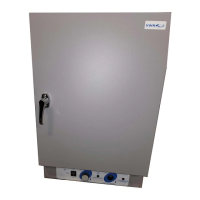
Description of the main power I/O switch and its position.
Pilot lamp indicates when heating elements are active.
Manually adjustable dial (0-10) for setting temperature.
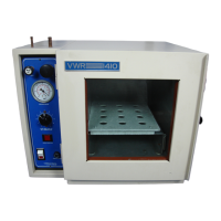
Valve on the right panel to control vacuum pump connection.
Valve on the left panel for vacuum release to atmospheric pressure.
Component indicating chamber operating pressure in inches of mercury.
Do not place or use explosive, combustible, or flammable materials in the oven.
Do not use sealed containers in the oven chamber.
Do not cut or remove the ground prong or use an ungrounded adapter plug.
Disconnect unit from power source before attempting repairs or component replacements.
If breakage occurs, all spilled mercury must be completely removed.
Oven is not suitable for use in Class I, II, or III locations as defined by NFPA 70.
Oven is not intended or usable as a patient connected device.
Use vacuum tubing for hookups; other types may collapse and prevent evacuation.
Advised pump capacity is four times the chamber volume.
Attach hose, close VENT, open VACUUM valve, start pump, latch door.
Gauge shows pressure from 0 to 30 inches Hg; oven can reach pressures as low as 10 microns.
Open VENT valve slowly to return chamber to atmospheric pressure.
Connect service cord to grounded outlet and push power switch to I/ON.
Place reference thermometer in chamber, viewable through window.
Adjust control dial to desired temperature, allow unit to heat and stabilize.
Disinfect oven interior regularly; remove and clean shelves and gasket.
Remove shelves, latch door, screw in leveling feet for storage or transport.
No maintenance required on electrical components; refer to troubleshooting if issues arise.
Addresses issues with temperature being too high, too low, or unit not heating.
Addresses issues related to door sealing and vacuum holding.
Covers blown fuses, unit not turning on, smoking, or chamber contamination.
| Brand | VWR International |
|---|---|
| Model | 1410 |
| Category | Oven |
| Language | English |