29
Installation
5.2.4 End of Line Testing without TOOLBOX PLUS™ Software
5.2.4.1 Sensor Installation
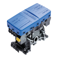
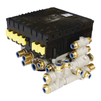
1. Look at the control port on the ECU/dual modulator valve assembly. Ensure that the connectors are
routed to the correct wheel-end location for a standard semi-trailer, as follows:
ECU/Dual Modulator Valve Assembly Mounted with Control Port Facing Front of Trailer
2S/2M
• Connect curbside sensor at D.
• Connect roadside sensor at C.
4S/2M*
• Connect curbside front sensor at D.
• Connect curbside rear sensor at F.
• Connect roadside front sensor at C.
• Connect roadside rear sensor at E.
4S/3M*— Sensor locations vary by type of installation. Refer to the diagrams for specifi c sensor
locations.
• Connect curbside sensor at D.
• Connect curbside sensor at F.
• Connect roadside sensor at C.
• Connect roadside sensor at E.
ECU/Dual Modulator Valve Assembly Mounted with Control Port Facing Rear of Trailer
2S/2M
• Connect curbside sensor at C.
• Connect roadside sensor at D.
4S/2M*
• Connect curbside front sensor at C.
• Connect curbside rear sensor at E.
• Connect roadside front sensor at D.
• Connect roadside rear sensor at F.
4S/3M*— Sensor locations vary by type of installation. Refer to the diagrams for specifi c sensor
locations.
• Connect curbside sensor at C.
• Connect curbside sensor at E.
• Connect roadside sensor at D.
• Connect roadside sensor at F.
* If the lift axle is sensed in 4S/2M and 4S/3M installations: Sensors E and F must always be used on the lift
axle to avoid an unwanted ABS indicator lamp illumination.
2. If sensors are not correctly installed, perform the necessary repairs.