3 Diagnostics, Troubleshooting and Testing
25
WABCO Maintenance Manual MM-0112 (Revised 07-18)
Modulator Valve Testing
Electrical Checks
앫 Check modulator valve by itself for resistance. Figure 3.16 and
Figure 3.17.
앫 Check ECU harness and modulator valve together for resistance.
Figure 3.18 and Figure 3.19.
앫 Verify no change in resistance or open circuit between valve by
itself and through harness.
앫 Check harness by itself for any shorts to battery and shorts to
ground.
앫 Measurements should read as follows:
NOTE: If resistance exceeds 9.0 ohm for 12V system (21.0 ohm for
24V system), verify the reading was not taken between the inlet and
outlet. If the correct pins were tested, clean the electrical contacts at
the modulator and retest.
Figure 3.16
Figure 3.17
Frame-Mounted
With ESC
LF X2-Green 17 and 18
RF X2-Green 5 and 6
LR X3-Green 1 and 2
RR X3-Green 3 and 4
LR (3rd axle) X4-Brown 3 and 4
RR (3rd axle) X4-Brown 5 and 6
Location Measurement
Inlet valve pin to Ground 4.0-9.0 ohm for 12V system
11.0-21.0 ohm for 24V system
Outlet valve pin to Ground 4.0-9.0 ohm for 12V system
11.0-21.0 ohm for 24V system
At ECU harness pins with
modulator valve connected
Same as above, no more than 1
ohm difference
ECU harness by itself for battery
voltage or ground
No continuity
ECU Sensor Connector Pins
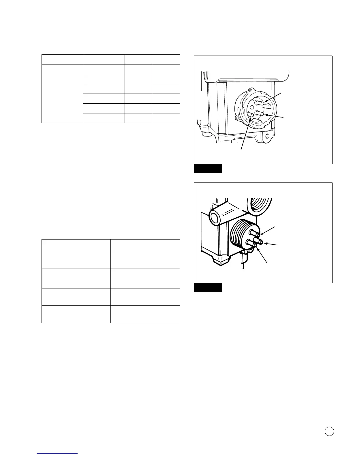
Figure 3.16
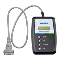
Figure 3.17
BAYONET-STYLE CONNECTOR
4004022a
EXHAUST SOLENOID
(BLUE WIRE)
INLET SOLENOID
(BROWN WIRE)
GROUND TERMINAL
OPEN-STYLE CONNECTOR
GROUND
TERMINAL
EXHAUST SOLENOID
(BLUE WIRE)
INLET SOLENOID
(BROWN WIRE)
4004021a