3 Diagnostics, Troubleshooting and Testing
34
WABCO Maintenance Manual MM-0112 (Revised 07-18)
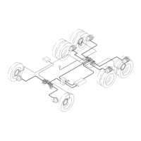
Figure 3.34
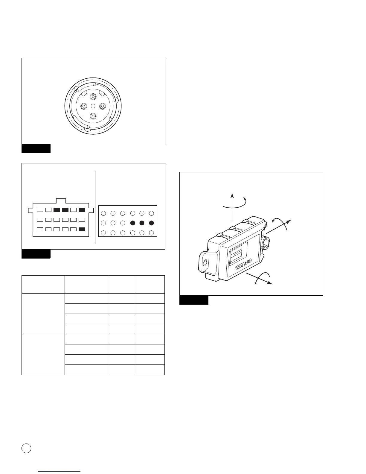
Figure 3.35
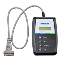
ESC Module Mounting
The ESC module contains sensors which measure both lateral
acceleration and yaw rate. Thus, it is critical that the module is
securely mounted, leveled and in correct location to the vehicle and
that the module is mounted as expected by the ECU and as per
vehicle OEM specifications.
The module should be installed in a manner where the label is right
side up. The module must be mounted perpendicular to the vehicle
frame rails on a cross member or cross member bracket. The
module connector could be facing the front or rear of the vehicle
depending on the OEM’s specified mounting. It is critical that the
unit be mounted in the exact location and manner as originally
installed by the vehicle manufacturer. Figure 3.36.
Figure 3.36
ESC Information Available in WABCO TOOLBOX™
Software 11 or Higher
ESC Information can be accessed through WABCO TOOLBOX™
Software 11 or higher under Components, ESC.
To access the ESC Information:
앫 If you are using TOOLBOX™ Software version 11 or higher, click
on the “Components” button. A drop-box will appear. Select
“ESC” then select “ESC Info”. Figure 3.37 and Figure 3.38.
Figure 3.34
Figure 3.35
ECU
ESC Module
Circuit Connector Pins
Cab-Mounted
Universal with ESC
Power Supply X4-18 pin 7
Ground X4-18 pin 10
ESC CAN-Low X4-18 pin 1
ESC CAN-High X4-18 pin 3
Frame-Mounted
With ESC
Power Supply X2-Green 9
Ground X2-Green External
ESC CAN-Low X2-Green 7
ESC CAN-High X2-Green 8
4012659a
1
3
2
4
ESC MODULE CONNECTOR
4007215a
CAB MOUNT ECU:
LOOKING INTO WIRE
HARNESS CONNECTOR
1
2
3
4
5
6
7
8
9
10
11
12
13
14
15
16
17
18
X4
FRAME MOUNT ECU
WITH ESC:
LOOKING INTO WIRE
HARNESS CONNECTOR
12
3456
71012 911 8
131618 1517 14
X2-GREEN
Figure 3.36
4010609a
± 5°
-5°
Z
+2°
-2°
Y
+2°
-2°
X