4 Component Replacement
46
WABCO Maintenance Manual MM-0112 (Revised 07-18)
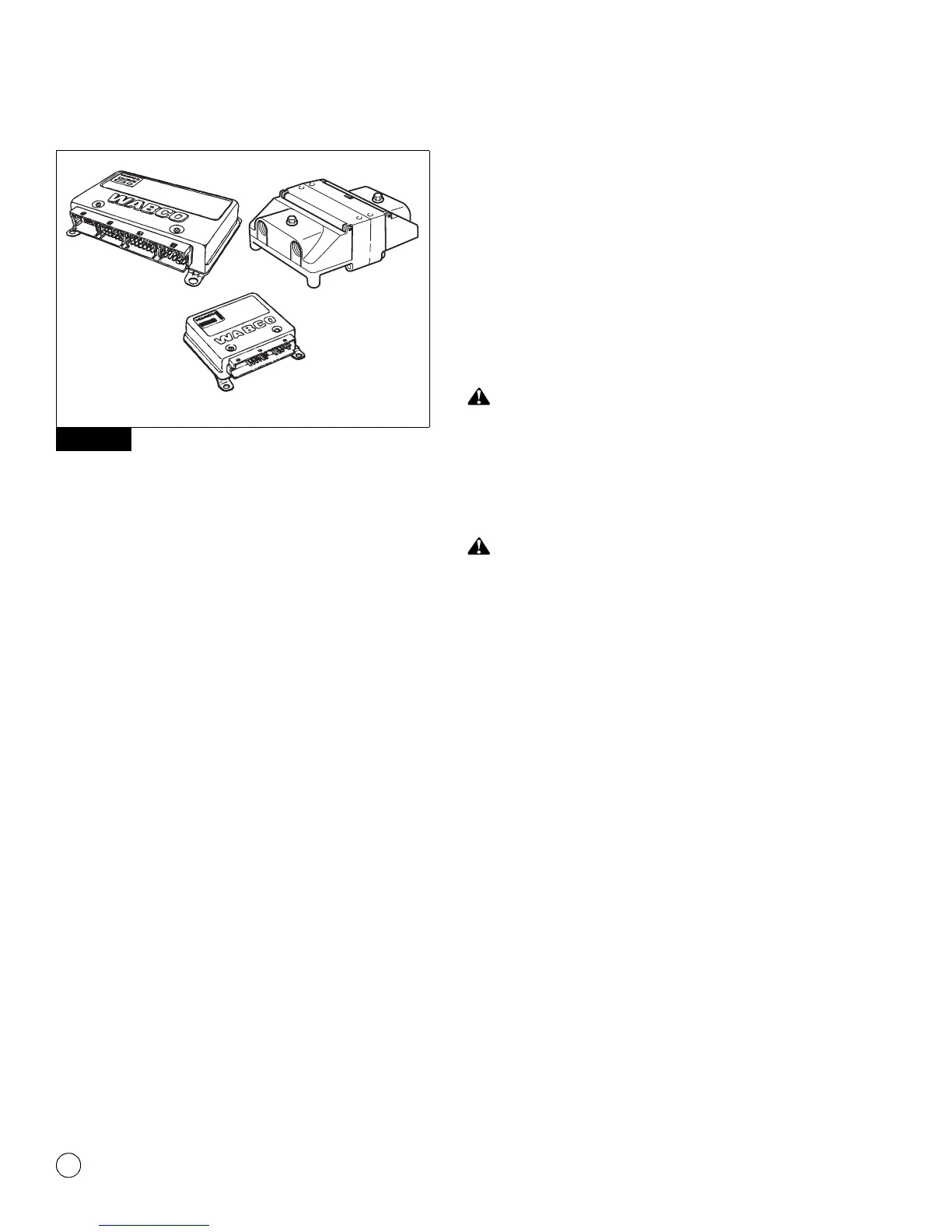
Figure 4.13
Installation
1. Install the ECU using the manufacturer’s mounting hardware.
Tighten the hardware per the manufacturer’s recommendation.
2. Install the wiring harness connectors to the ECU.
3. Remove the blocks.
4. Test the installation.
NOTE: If ECU has roll stability control (RSC), mounting of the
ECU is crucial for proper operation due to internal
accelerometer. Note the location installation of the ECU before
removal. After installing ECU, verify the ECU is properly leveled
and securely mounted on the right location as per OEM specs.
See Section 2 RSC components for further information.
Testing the Installation
To test the ECU installation:
1. Turn the ignition ON and verify that the ABS self test and ABS
light comes on and goes off.
앫 Wheel speed related faults require a vehicle speed over 4
mph before the ABS light turns off and the code clears.
2. Use TOOLBOX™ Software to verify system has no active
faults.
앫 ECUs with Electronic Stability Control (ESC) will require
system to be calibrated whenever a component has been
replaced.
앫 Follow the ESC End of Line Calibration Procedure described
in this manual.
앫 When the ESC End of Line Calibration Procedure is
completed, the ABS and ATC/ESC lamps should come on
and go back off when ignition power is turned on. The ATC/
ESC lamp may remain on briefly after the ABS lamp goes
off.
3. There should not be any active faults displayed in the ECU
memory.
Steering Angle Sensor (SAS) — WABCO Only
Removal
Park the vehicle on a level surface. Block the wheels to
prevent the vehicle from moving. Support the vehicle with
safety stands. Do not work under a vehicle supported only by
jacks. Jacks can slip or fall over. Serious personal injury and
damage to components can result.
If equipped, disable the supplemental restraint system (air
bag) to avoid serious personal injury. Refer to the vehicle
manufacturer’s service publication for further information.
1. Center the steering wheel with the front wheels positioned
straight ahead.
2. Turn the ignition switch to the OFF position. Apply the parking
brake.
3. Place blocks under the front and rear tires to prevent the
vehicle from moving.
4. Locate the SAS on the steering column shaft, either near the
universal joint on the bottom of the column or under the
steering wheel near the top of the column.
5. If the SAS is located at the top of the steering column, remove
the vehicle steering wheel using the recommended steering
wheel puller.
6. The SAS is attached by three screws to the steering column
with the center tab located in the grooved steering column
shaft. Figure 4.14.
Figure 4.13
UNIVERSAL
ECU
FRAME-MOUNTED
ECU
BASIC
ECU
4003974a