4 Component Replacement
47
WABCO Maintenance Manual MM-0112 (Revised 07-18)
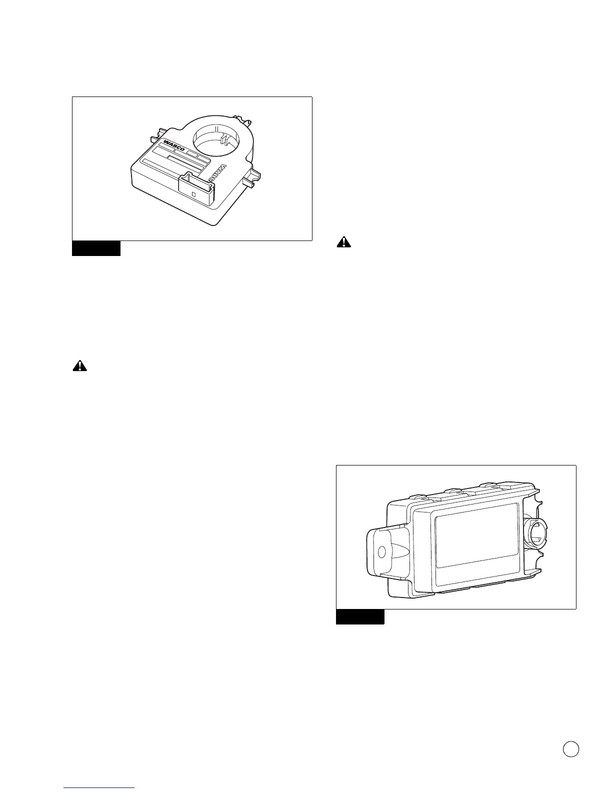
Figure 4.14
7. Disconnect the wiring harness connector from the SAS. (Note
the position of the connector either facing up or down.)
8. Remove the attaching screws and slide the SAS off of the
steering column shaft.
Installation
If the SAS is not installed in the correct orientation, it will not
function correctly and may become damaged.
1. Apply a small amount of the supplied grease to the tab in the
center of the SAS and to the machined groove on the steering
shaft.
2. Install the SAS with the connector facing the same direction as
the original. Place the SAS over the steering column shaft and
slide it into place with the SAS tab placed in the groove that is
machined on the steering column shaft.
3. Using the new furnished screws, replace the attaching screws
and tighten to a maximum of 22 in-lb (2.5 N폷m).
@
4. Install the SAS wiring harness connector by pushing the
connector together until the small tab snaps into place.
5. Install the steering wheel and tighten per the manufacturer’s
recommendation.
6. Remove the blocks.
7. Test the installation.
Test the Installation
To test the SAS installation, the system must be calibrated.
1. Follow the ESC End of Line Calibration Procedure described in
this manual.
2. When the ESC End of Line Calibration Procedure is completed,
the ABS and ATC/ESC lamps should come on and go back off
when ignition power is turned on. The ATC/ESC lamp may
remain on briefly after the ABS lamp goes off.
3. There should not be any active faults displayed in the ECU
memory.
Electronic Stability Control (ESC) Module
Removal
Park the vehicle on a level surface. Block the wheels to
prevent the vehicle from moving. Support the vehicle with
safety stands. Do not work under a vehicle supported only by
jacks. Jacks can slip and fall over. Serious personal injury and
damage to components can result.
1. Turn the ignition switch to the OFF position. Apply the parking
brake.
2. Place blocks under the front and rear tires to prevent the
vehicle from moving.
3. If necessary, raise the vehicle off the ground and place safety
stands under the vehicle.
4. Disconnect the wiring harness connector from the ESC module.
Figure 4.15 and Figure 4.16.
Figure 4.15
Figure 4.14
Figure 4.15
4010604a
WARNING
DO NOT MOVE OR RELOCATE