3 Diagnostics, Troubleshooting and Testing
35
WABCO Maintenance Manual MM-0112 (Revised 07-18)
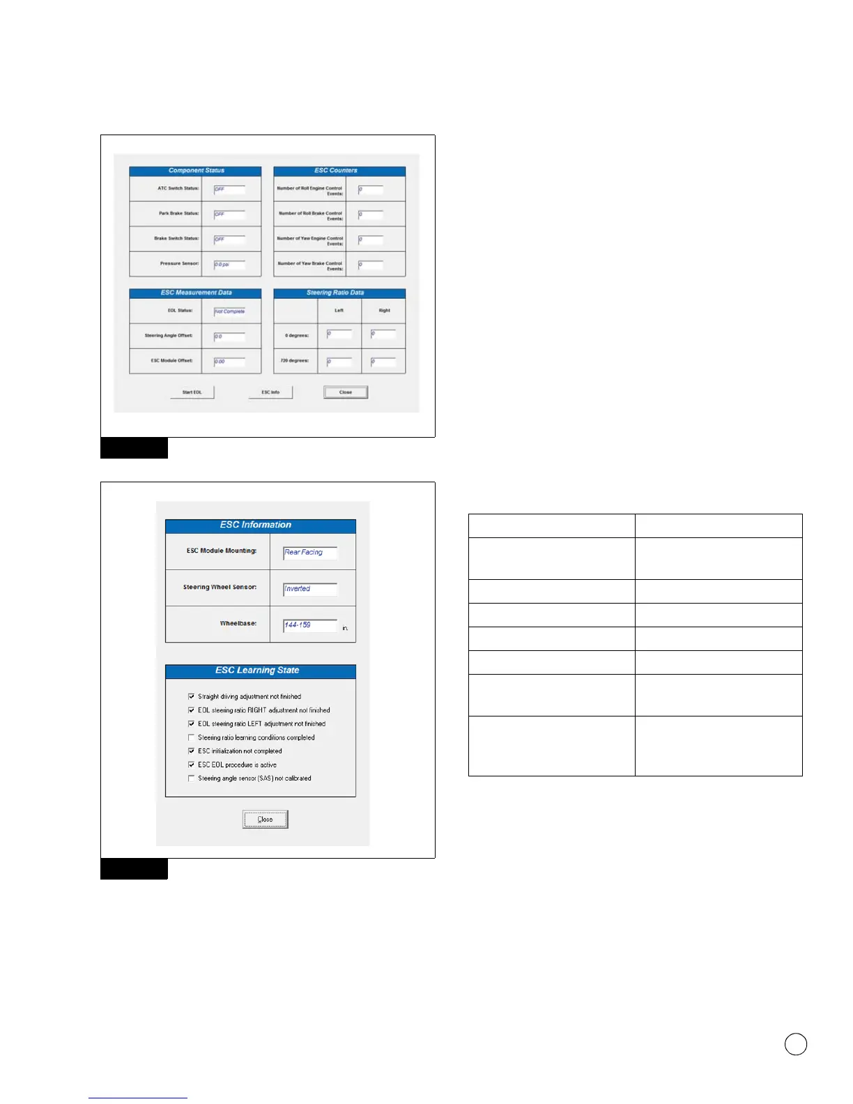
Figure 3.37
Figure 3.38
Steering Angle Sensor (SAS) Testing
Electrical Checks
The following tests are for WABCO SAS Only.
앫 Disconnect SAS and check terminating resistance across Pin 1
and Pin 2 of the SAS. Figure 3.39 and Figure 3.40.
For the following checks, all the ECU and ESC module connectors
must be plugged in as the ECU provides all voltage, ground and CAN
communications. Figure 3.42 and Figure 3.43.
앫 Take measurements at the SAS harness connector side.
Figure 3.41.
— Check Key On CAN Low voltage on Pin 1.
— Check Key On CAN High voltage on Pin 4.
— Check Key On Voltage Supply on Pin 5.
— Check Key Off resistance across CAN low Pin 1 and CAN
High Pin 4.
NOTE: For correct sensor operation, there must be a jumper wire on
the harness side across either Pin 2 to Pin 3 or Pin 4 so terminating
resistor is connected as shown in Figure 3.40.
Figure 3.37
Figure 3.38
Location Measurement
Wabco SAS terminating resistor
on sensor
Approximately 180 ohms
CAN High Voltage 2.5-5.0V
CAN Low Voltage 0.1-2.4V
Voltage Supply to Ground 8.0-16.0V
ESC CAN-High to ESC CAN-Low Approximately 90 ohm
SAS harness jumper (Pin 2 to
Pin 4 or Pin 2 to Pin 3)
Continuity
ESC CAN-High or CAN-Low to
Power or Ground (with ECU, ESC
Module and SAS unplugged)
No continuity