4 Component Replacement
43
WABCO Maintenance Manual MM-0112 (Revised 07-18)
Figure 4.6
Figure 4.7
5. Remove the mounting bolts from the valve package. Remove
the valve package from the vehicle.
6. Replace the ABS valve package: Tighten the bolts to the
vehicle manufacturer’s recommendation. Remove the blocks
and safety stands as necessary.
7. Test the installation.
Removal and Installation — Component Valves
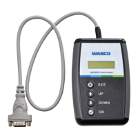
1. Remove the ABS valve package from the vehicle. Figure 4.8.
Figure 4.8
2. Use a 6 mm Allen wrench to loosen and remove the Allen-head
bolts.
3. Carefully separate the ABS modulator valve(s) from the relay or
quick release valve.
4. Remove and discard old O-rings. Lubricate replacement
O-rings with the grease provided.
5. Plug any unused ports on the replacement valve(s).
6. Attach the ABS modulator valve(s) to the relay or quick release
valve. Use a 6 mm Allen wrench to tighten the Allen-head bolts
to 13-15 lb-ft (18-20 N폷m).
@
7. Replace the ABS valve package: Tighten the bolts to the
vehicle manufacturer’s recommendation. Remove the blocks
and safety stands as necessary.
8. Check the valves for leaks:
앫 Modulator valve(s). Refer to the procedure for checking the
modulator valve installation in this section.
앫 Relay or quick release valve. Refer to the procedure for
checking the quick release or relay valve installation in this
section.
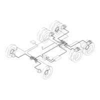
Figure 4.6
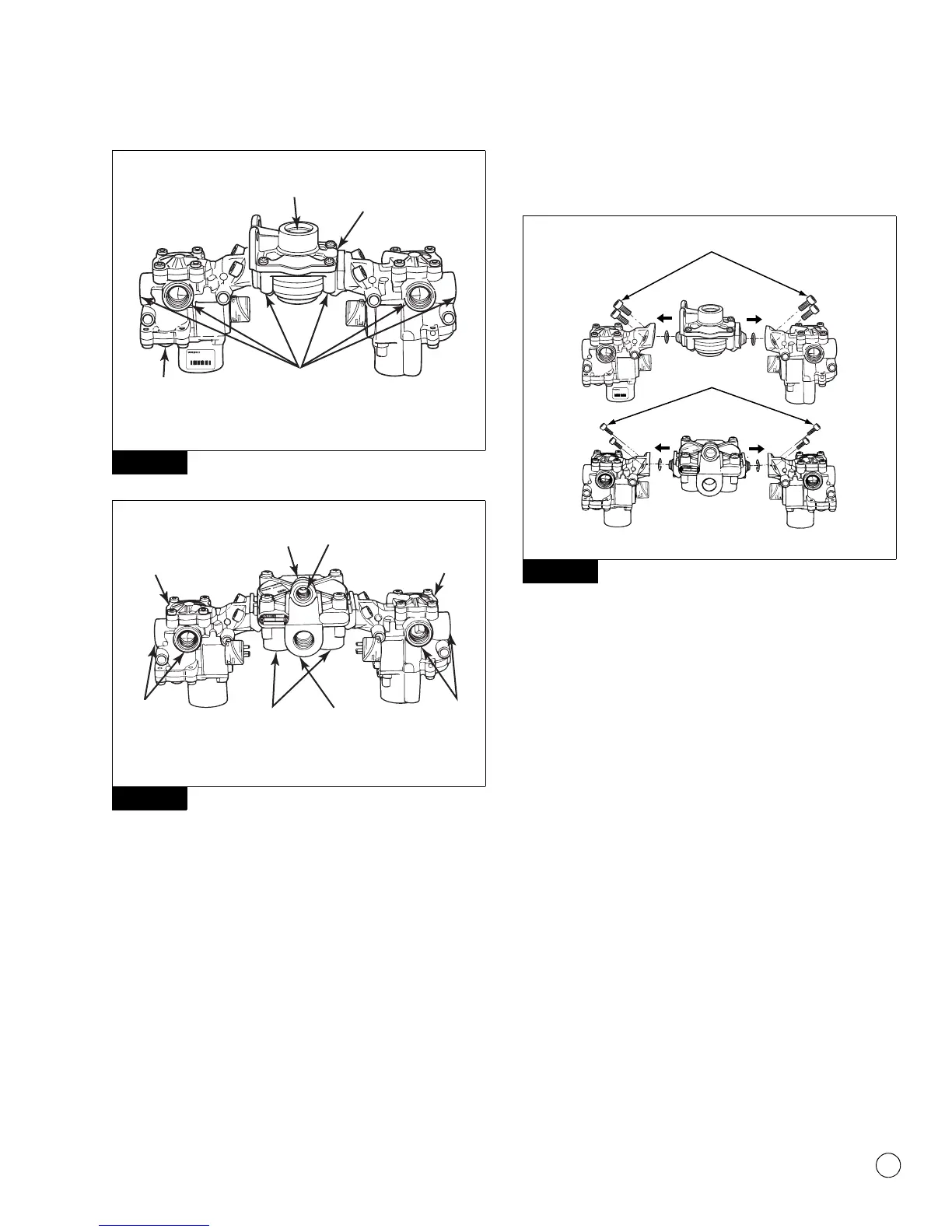
Figure 4.7
4007847a
472 500 30. 0
MADE IN GERMANY
001 20/98
SUPPLY PORT
1/2" NPT
QUICK RELEASE
VALVE
1/2" NPT
DELIVERY
PORTS
MODULATOR
VALVE
ABS QUICK RELEASE VALVE PACKAGE
4007848a
ABS
MODULATOR
VALVE
RELAY
VALVE
CONTROL
PORT
1/4" NPT
ABS
MODULATOR
VALVE
DELIVERY
PORTS
1/2" NPT
DELIVERY
PORTS
1/2" NPT
SUPPLY
PORT
1/2" NPT
DELIVERY
PORTS
3/8" NPT
ABS RELAY VALVE PACKAGE
Figure 4.8
xxxxx xxxxx
xxxxx xxxxxxxxxx xxxxx
1002041c
472 500 30. 0
MADE IN GERMANY
001 20/98
ALLEN-HEAD BOLTS
ALLEN-HEAD BOLTS
13-15 LB-FT
(18-20 N•m)
13-15 LB-FT
(18-20 N•m)