Do you have a question about the Wacker Neuson DPU 2950 and is the answer not in the manual?
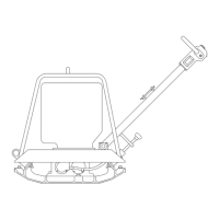
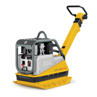
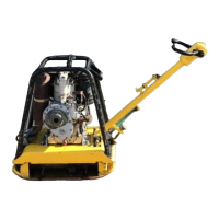
The Wacker DPU 2950/2960/2970 vibratory plate is a robust piece of construction equipment designed for compaction tasks. This operator's manual provides essential information for the safe and effective use, maintenance, and transport of these machines.
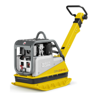
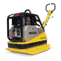
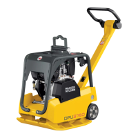
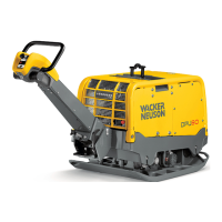
The DPU 2950, DPU 2960, and DPU 2970 models are vibratory plates primarily used for compaction jobs. They are engineered to compact various types of soils, including cohesive soils, in both trench and surface compaction applications. Beyond soil, these machines are also suitable for compacting blacktop surfacings and for vibrating interlocking paving stones. The DPU 2950 is highlighted as the most universally applicable machine in this series due to its optimal ratio of centrifugal force to contact area. The DPU 2960 and DPU 2970 models are utilized when a higher area capacity is required.
The power transmission system of these vibratory plates involves a drive engine, a centrifugal clutch, and V-belts, which directly transfer power to the exciter. The exciter generates vibrations, essential for the compaction process. The drive motor is an air-cooled, single-cylinder, 4-stroke diesel engine.
Operating the vibratory plate requires adherence to specific safety instructions to prevent bodily injuries and ensure efficient operation. Operators must be at least 18 years of age, physically and mentally fit, and have received proper instruction and demonstrated ability in guiding vibratory plates. The employer is responsible for assigning individuals to operate these machines and providing additional instructions for extraordinary uses.
During operation, the functioning of operating levers or elements must not be influenced or rendered ineffective, and the operator must remain at the control elements. Before breaks, the engine must be stopped, and the machine positioned to prevent it from turning over.
Fuel handling requires particular care: the engine must be stopped before refueling, and fuel should not come into contact with hot engine parts or spill onto the ground. Smoking and open flames are strictly prohibited near the machine. The tank lid must be tightly fitted, and the fuel cock, if available, should be shut off when stopping the engine. For long-distance transport, the fuel tank must be completely drained. Leaky fuel tanks pose an explosion risk and must be replaced immediately. The machine should not be operated in areas where explosions may occur.
When operating in enclosed areas, tunnels, adits, and deep trenches, sufficient fresh air must be ensured. Operators must keep hands, feet, and clothes away from moving parts and wear safety shoes and eye protection, especially in trench operations where sand and stones may be ejected. When working near edges of breaks, pits, slopes, trenches, and platforms, the vibratory plates must be operated to avoid turning over or dropping in.
The soil or subsoil to be compacted must have adequate load-carrying capacity. Appropriate protective clothing should be worn during operation and maintenance. When traveling backward, the operator must guide the vibration plate laterally using the guide handle to avoid being squeezed between the handle and obstacles. Special care is needed on uneven ground or when compacting coarse material, ensuring a firm stance. Vibratory plates must be guided to prevent hand injuries from solid objects and to ensure their stability. Machines with integrated transport trolleys are for transport only and should not be used for parking or storage.
Starting the engine involves several steps: opening to full throttle, placing the decompression lever in a vertical position, pulling the starter knob, inserting the starting crank, and turning the automatic decompression lever approximately 90 degrees until a clicking sound indicates engagement. The operator should stand sideways to the engine, feet slightly apart, and brace themselves with one hand on the equipment while turning the crank with the other. A firm grip on the crank handle is crucial to prevent sudden slippage. The crank should be turned slowly at first until it catches, then faster. When the automatic decompression lever returns to its vertical position, the highest crank turning speed should have been reached, and the engine should fire up and reach maximum RPMs. The starter knob automatically returns to its initial position. If cranking is too slow, the engine may start in the wrong direction, leading to air being sucked through the exhaust and the air filter becoming an exhaust, posing a fire hazard. In such cases, the engine must be turned off, and the cranking procedure restarted. The starting crank should be removed as soon as the engine runs, and the engine RPMs set to idle. The engine should warm up for 7 minutes before starting compaction work. Starting aids like sprays are forbidden due to safety risks.
Regular maintenance is crucial for trouble-free operation and extended machine life. All external screw connections should be checked for tightness approximately 8 hours after the first operation. Only original spare parts should be used, and any modifications, including engine speed adjustments, require express approval from Wacker to maintain liability. All drive units must be switched off before maintenance, unless the task specifically requires a running engine. For machines with electric starters, the battery must be disconnected before working on electrical parts. Pressure must be removed from hydraulic lines before working on them, taking care as the oil can be very hot (over 80°C) and to prevent splashing into the operator's eyes. All safety devices must be properly reinstalled after maintenance. The machine should not be hosed down with water after use, and high-pressure washers or chemical products should be avoided.
The maintenance schedule includes daily checks of the oil bath air filter (oil level, dirt, cleaning/topping up) and dry-type air filter (visual display, cleaning/replacement). The engine oil level should be checked and topped up daily, along with checking the crank and crank carrier fastening and exciter tightness. The first engine oil change is recommended after 25 hours, with subsequent changes every 150 hours. The moveable locking device and spindle for pole height adjustment should be greased weekly. Monthly checks include the tow-bar head oil level, V-belt tension, and fastening screws of the protective frame and central suspension. After 150 hours, further engine oil changes are due, cooling fins should be checked for dirt and cleaned, and all accessible screw connections tightened. The exciter oil should also be changed at this interval. Valve clearance should be checked and set to 0.1 mm when the motor is cold, and the injection nozzle function checked at 200 bars, both after 300 hours.
Adjusting V-belt tension is a critical initial adjustment after 5 to 20 hours of operation. This involves removing the belt guard, nuts, and V-belt pulley half, then removing the necessary number of spacers and installing them on the outside of the V-belt pulley to maintain alignment. Spring washers are installed to ensure the large diameter rests on the motor V-belt pulley, and nuts are tightened alternately under continuous rotation.
The exciter is filled with oil upon delivery, and the oil should be changed every 250 hours, using approximately 0.75 liters of SAE 10 W 40 oil. The oil level is correct when it reaches the lower flange of the threaded drain hole.
For hydraulic control, the oil level in the center pole head should be checked and topped up if necessary (to the mark when the center pole is vertical). Too much oil can hinder reverse motion, while insufficient oil reduces advance speed. Fuchs Renolin MR 520 hydraulic oil is recommended. The hydraulic system needs to be bled after topping up with oil. This involves placing the handle vertically, slightly pulling back and releasing the control lever, then opening the bleeding screw on the control housing until no air bubbles appear, and finally tightening the screw.
When disassembling exciter components, eccentric weights should be removed first and installed last during assembly. Toothed gears should be marked to ensure correct assembly, with eccentric weights pointing down and the piston at half stroke. Shafts should be blocked during eccentric weight assembly to prevent finger pinching, and all screws tightened to the prescribed torque.
When disassembling the center pole head, it's important to note that the piston is under spring tension. During assembly, the toothed rod must be located in the toothed gear so that the handle is set at 90 degrees to the center pole head when the piston is fully extended. After maintenance, a 5-minute test run is recommended to bleed air from the system.
Valve clearance adjustment (0.1 mm when cold) involves placing the decompression lever downwards, removing the cylinder head cover, turning the motor until compression resistance is felt, checking clearance with a feeler gauge, and adjusting the setting screw if necessary. The decompression device can also be adjusted by removing the cylinder head cover, turning the motor until compression resistance is felt, turning the decompression lever to its locked position (approx. 60 degrees), loosening the locking nut and setting screw, then turning the setting screw until the rocker arm touches the valve stem, and finally turning it an additional 1/4 turn before locking.
For starting at very low temperatures (below -5°C), the starting oil dosage device should be used (up to 2 dosages for engines up to 6 kW (8 HP), and up to 3 dosages for engines over 6 kW (8 HP)). A higher than recommended dosage could lead to a back-swing of the crank. Before attempting to start in cold conditions, inserting the crank, turning the automatic decompression lever to the first notch, and turning the engine "free" (decompressed) 10 to 20 times can reduce resistance by changing the lubricating oil's viscosity and ensure proper injection nozzle function.
| Model | DPU 2950 |
|---|---|
| Manufacturer | Wacker Neuson |
| Category | Power Tool |
| Frequency | 90 Hz |
| Frequency (Hz) | 90 Hz |
| Engine Model | Honda GX160 |
| Fuel Type | Gasoline |
| Vibration Isolation | Yes |
| Type | Vibratory Plate |
| Centrifugal Force (lbf) | 6, 744 lbf |
| Working Width | 600 mm |
| Operating Width (in) | 24 |
| Max. Compaction Depth | 600 mm |
| Travel Speed | 30 m/min |
| Engine Type | Gasoline |
| Engine Power (kW) | 7.5 kW |
| Fuel Tank Capacity (L) | 12 L |