Troubleshooting Voltage Issues GPS 8500/GPS 9700
wc_tx000828gb.fm 28
3.10 Checking the Transformer
Prerequisites
Generator shut down
Multimeter
Background
The transformer consists of three windings. Each needs to be checked when
checking the condition of the transformer.
Procedure
Follow the procedure below to check the transformer.
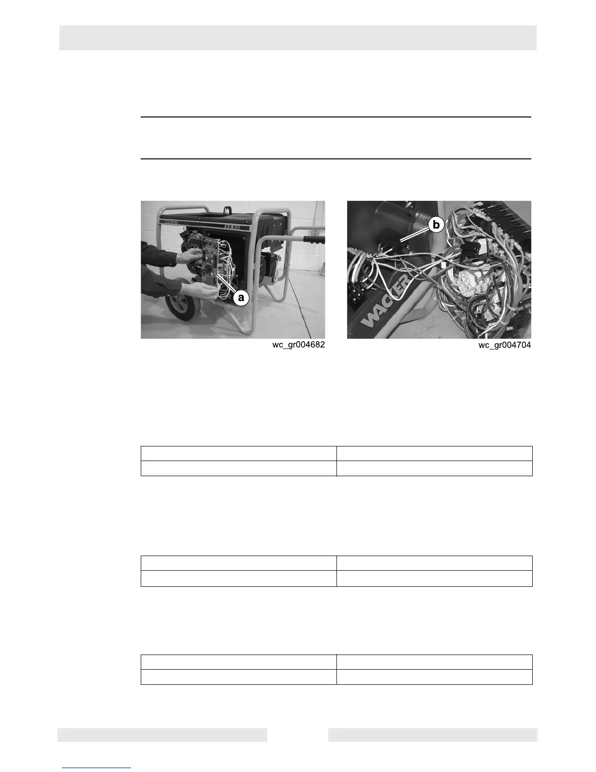
1. Remove the front panel (a) from the generator.
2. Locate the transformer (b) within the control box.
3. Trace the brown wire and the blue wire coming out of the transformer. The
brown wire runs to terminal 6 of the Voltage Selector Switch (VSS). The blue
wire runs to terminal 10 of the VSS.
4. Measure the resistance between the brown wire and the blue wire.
Is 810–890 Ohms measured?
5. Trace the red wire and the white wire coming out of the transformer. The red
wire runs to the main circuit breaker. The white wire runs to the neutral side of
the 125V GFCI receptacle.
6. Measure the resistance between the red wire and the white wire.
Is 630–690 Ohms measured?
7. Trace the orange wire and the yellow wire coming out of the transformer. Both
wires run to the Automatic Voltage Regulator (AVR).
8. Measure the resistance between the orange wire and the yellow wire.
Is 450–490 Ohms measured?
The transformer has now been checked. Continue by checking the VSS.
Yes ____ No ____
Continue. The transformer has failed; replace it.
Yes ____ No ____
Continue. The transformer has failed; replace it.
Yes ____ No ____
The transformer is OK. The transformer has failed; replace it.
 Loading...