Troubleshooting Voltage Issues GPS 8500/GPS 9700
wc_tx000828gb.fm 30
3.12 Checking the Auto Idle Circuit
Prerequisites
Machine’s battery must measure 12V
Multimeter
14-gauge jumper wire
Background
The idle is controlled by the engine electronic governor system (control module and
motorized actuator) and the switch and current transformer. Each component must
be checked.
Checking the
control
module
Follow the procedure below to check the control module.
1. Shut down the generator.
2. Disconnect all loads from the generator.
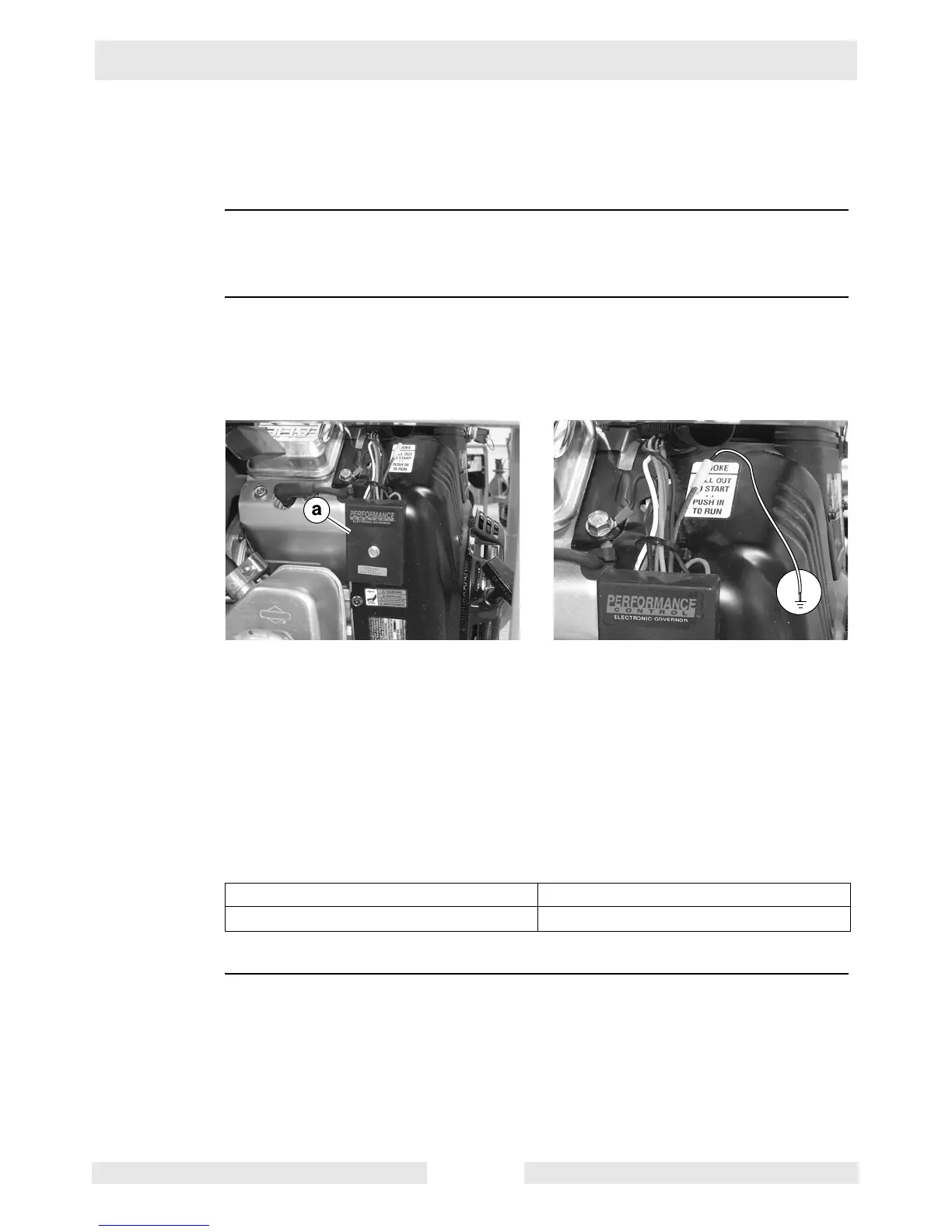
3. Locate the control module (a).
4. Remove the loom (harness) to expose the wires.
5. Disconnect the blue wire at the connector.
6. Start the engine.
7. Connect the jumper wire to the module’s blue wire and connect it to ground.
After a 10-second delay the engine should idle down to 1750 rpm.
8. Remove the ground wire.
The engine should return to 3600 rpm.
Does the module perform as stated above?
Checking the
actuator
Follow the procedure below to check the actuator.
1. Shut down the engine.
This procedure continues on the next page.
Yes ____ No ____
Continue. The module has failed; replace it.
wc_gr004701
 Loading...