Disassembly and Assembly GPS 8500/GPS 9700
wc_tx000829gb.fm 44
4.11 Removing and Installing the Electronic Governor
Prerequisites
Engine shut down
Engine cool
Removal
procedure
Follow the procedure below to remove the electronic governor.
1. Disconnect the red and green wires from the control module.
2. Remove the air cleaner assembly.
3. Disconnect the governor link at the carburetor.
4. Remove the governor control bracket with the actuator.
5. Disconnect the governor link from the actuator and remove the throttle return
spring.
6. Remove the screws, nuts, and actuator from the control bracket.
Installation
procedure
Follow the procedure below to install the electronic governor.
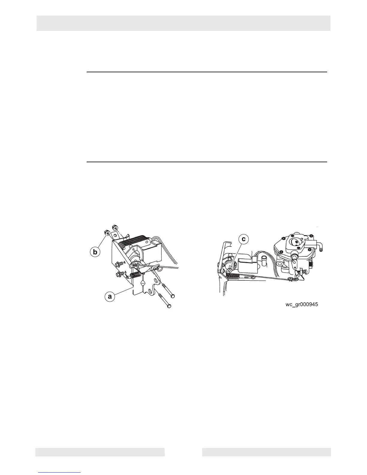
1. Assemble the actuator to the governor control bracket (a).
Torque the screws (b) to 3.4 Nm (30 in. lbs.).
Note: Hold the long screws with a 1/4-inch wrench when torquing the nuts. The
screws must not turn while torquing the nuts.
2. Connect the governor link to the actuator. Make sure the link snaps into the hole
in the actuator grommet.
3. Connect the throttle return spring through the slot in the governor control
bracket with the open end spring facing out and through the small hole in the
governor bracket.
4. Connect the governor control bracket assembly to the engine.
Torque the four 8 mm screws to 17 Nm (150 in. lbs.).
Torque the two 6 mm screws to 10 Nm (70 in. lbs.).
5. Rotate the actuator lever to the position shown (c) and connect the governor link
to the carburetor.
6. Connect the red and green wires to the control module.
THe procedure to remove and install the electronic governor is now complete.
 Loading...