7 Components and operator's controls
100_0101_cp_0011.fm 20
7 Components and operator's controls
7.1 Components and operator's controls of the drive motor
T-Handle
The t-handle has different colors for the different versions, see chapter Technical Data.
With the t-handle, the quick disconnect coupling is opened so as to allow for a quick replacement and a
secure connection link of the flexible shaft to the drive motor.
Air inlet and outlet
Airflow enters into the housing of the drive motor through the air cleaner element, cools the electric motor
and exits through the ventilation slots. The airflow is represented by arrows in the drawing.
7.2 Components of the HMS
Depending on the application conditions, you can combine these components in different designs.
You can find information about the assembly of an HMS in the chapter Permissible combinations.
The HMS is composed of the following components:
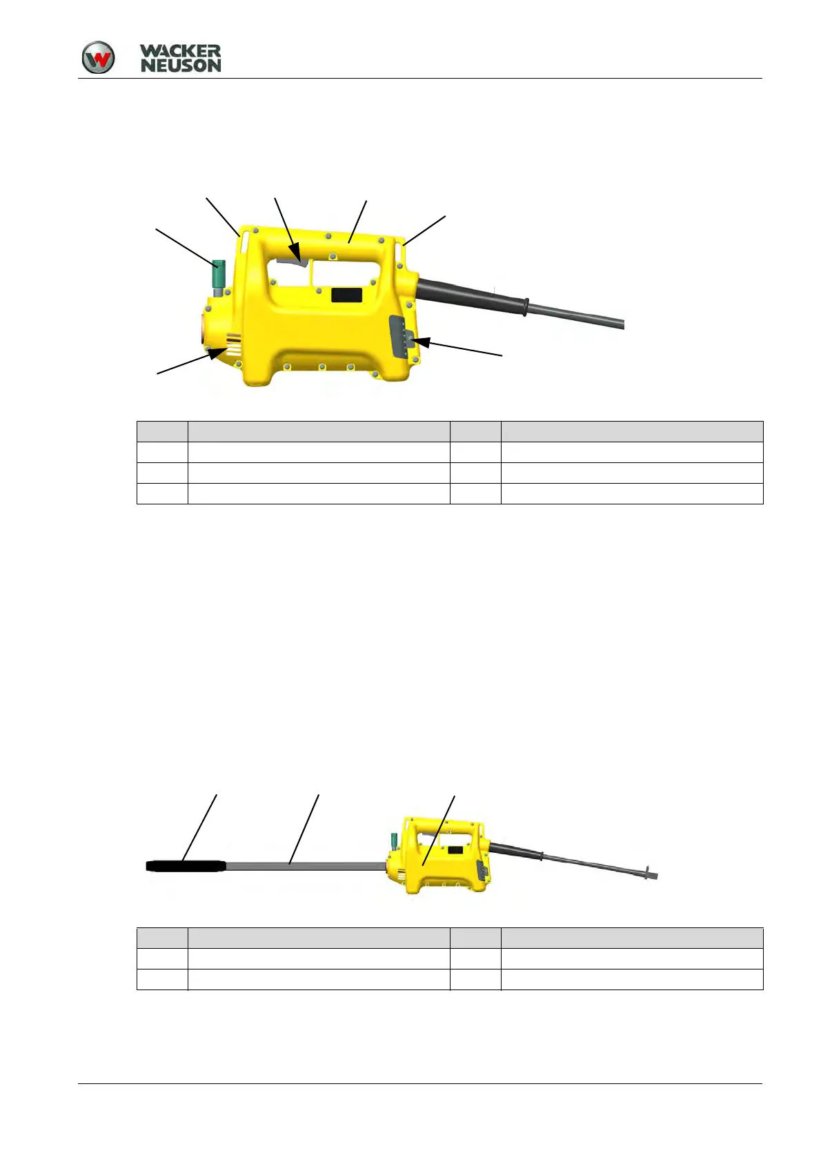
Item Designation Item Designation
1 ON/OFF switch 4 Air outlet
2 Handle 5 T-Handle
3 Air inlet 6 Lugs for shoulder strap
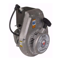
Item Designation Item Designation
1 Vibrator head (optional) 3 Drive motor
2 Flexible shaft (optional)