84 Function Description WAGO-I/O-SYSTEM 750
750-880, 750-880/025-000 ETHERNET Programmable Fieldbus Controller
Manual
Version 1.0.1
Pos: 75.9 /Serie 750 (W AGO-I/O-SYSTEM)/Funk tionsbeschreibung/Da tenaustausch/ Speicherbereic he MODBUS/Speicherbereic he MODBUS - Bild (750-841, -881) @ 6\mod_1256046946781_21. doc @ 43245 @ 3 @ 1
7.3.1 Memory Areas
12
2
4
4
CPU
I
O
11
1
3
1
Programmable Fieldbus Controller
memory area
for input data
input
modules
IEC 61131-
program
memory area
for output data
fieldbus
master
I/O modules
word 1276
word 1531
word 0
word 255
word 256
MODBUS
PFC-OUT-
variables
word 511
word 1276
Ethernet IP
PFC-OUT-
variables
word 1531
word 1275
word 512
word 0
word 255
word 256
MODBUS
PFC-IN-
variables
word 511
word 512
word 1275
Ethernet IP
PFC-IN-
variables
input
modules
output
modules
output
modules
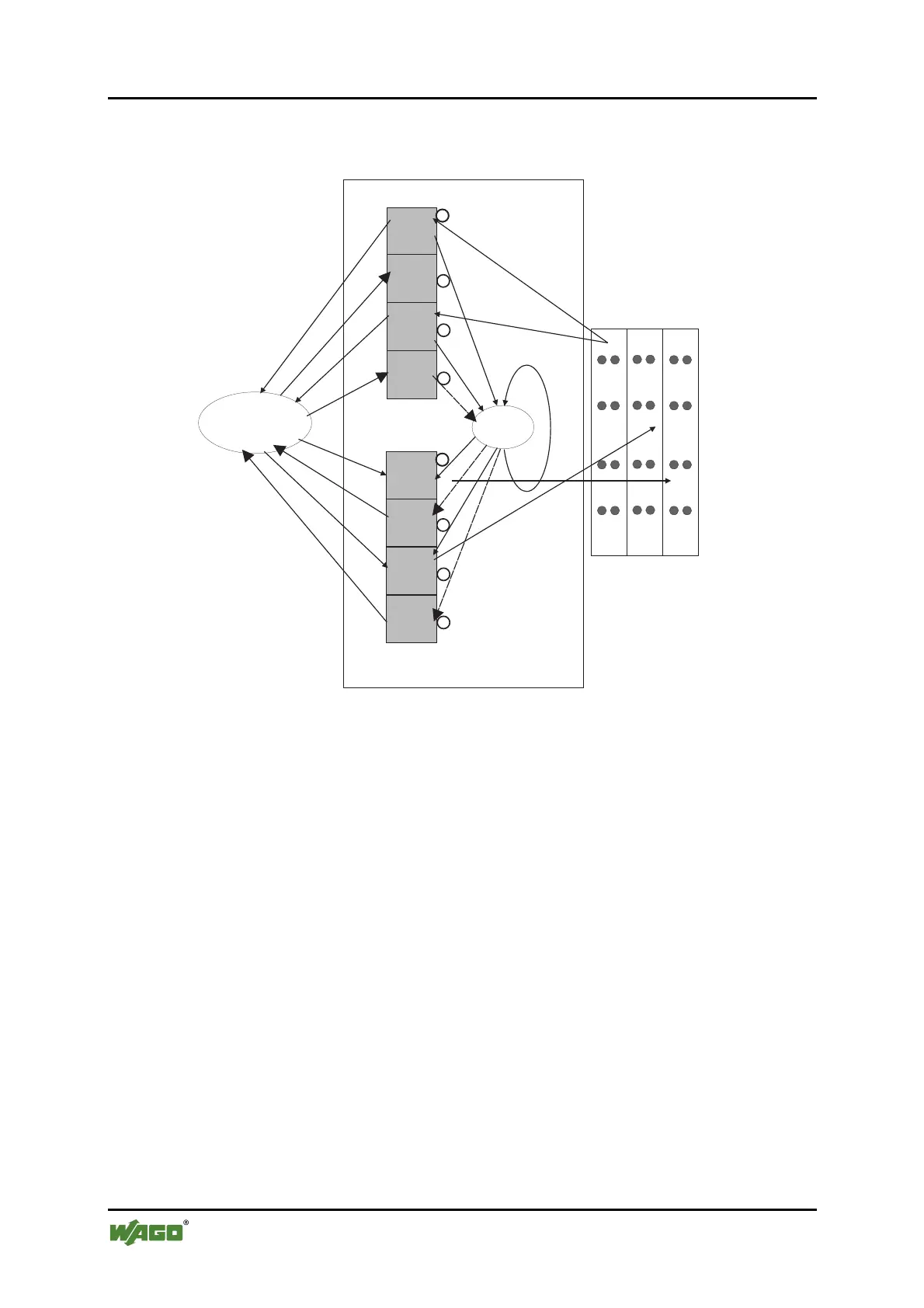
Figure 40: Memory areas and data exchange
Pos: 75.10 /Serie 750 (W AGO-I/O-SYSTEM)/Funk tionsbeschreibung/Da tenaustausch/ Speicherbereic he MODBUS/Speicherbereic he MODBUS - Legende "Speicherber eiche und Datenaustausc h" (Controller) @ 6\ mod_1256047253015_21.d oc @ 43248 @ @ 1
The controller process image contains the physical data for the bus modules.
These have a value of 0 ... 255 and word 512 ... 1275.
The input module data can be read by the CPU and by the fieldbus side.
Likewise, data can be written to the output modules from the CPU and the
fieldbus side.
The MODBUS PFC variables are stored in each of the memory areas for word
256 ... 511 between these sides.
The MODBUS-PFC input variables are written to the input memory area
from the fieldbus side and read in by the CPU for processing.
The variables processed by the CPU using the IEC-61131-3 program are
places in the output memory area, where they can be read out by the master.
Pos: 75.11 /Serie 750 (W AGO-I/O-SYSTEM)/Funk tionsbeschreibung/Da tenaustausch/ Speicherbereic he MODBUS/Speicherbereic he MODBUS - Im Anschluss an die Busk lemmendaten Wort 1276. ..1531 (750-841) @ 6\ mod_1256133822562_21.doc @ 43401 @ @ 1
The memory area for word 1276 ... 1531 for the Ethernet/IP PFC variables is
adjacent to the physical I/O module data.
Pos: 75.12 /Serie 750 (W AGO-I/O-SYSTEM)/Funk tionsbeschreibung/Da tenaustausch/ Speicherbereic he MODBUS/Speicherbereic he MODBUS - Für zukünftige Protok oll-Erweiterungen und weitere PFC-Vari ablen ist ... @ 6\mod_1256133965750_21.doc @ 43405 @ @ 1
 Loading...