11
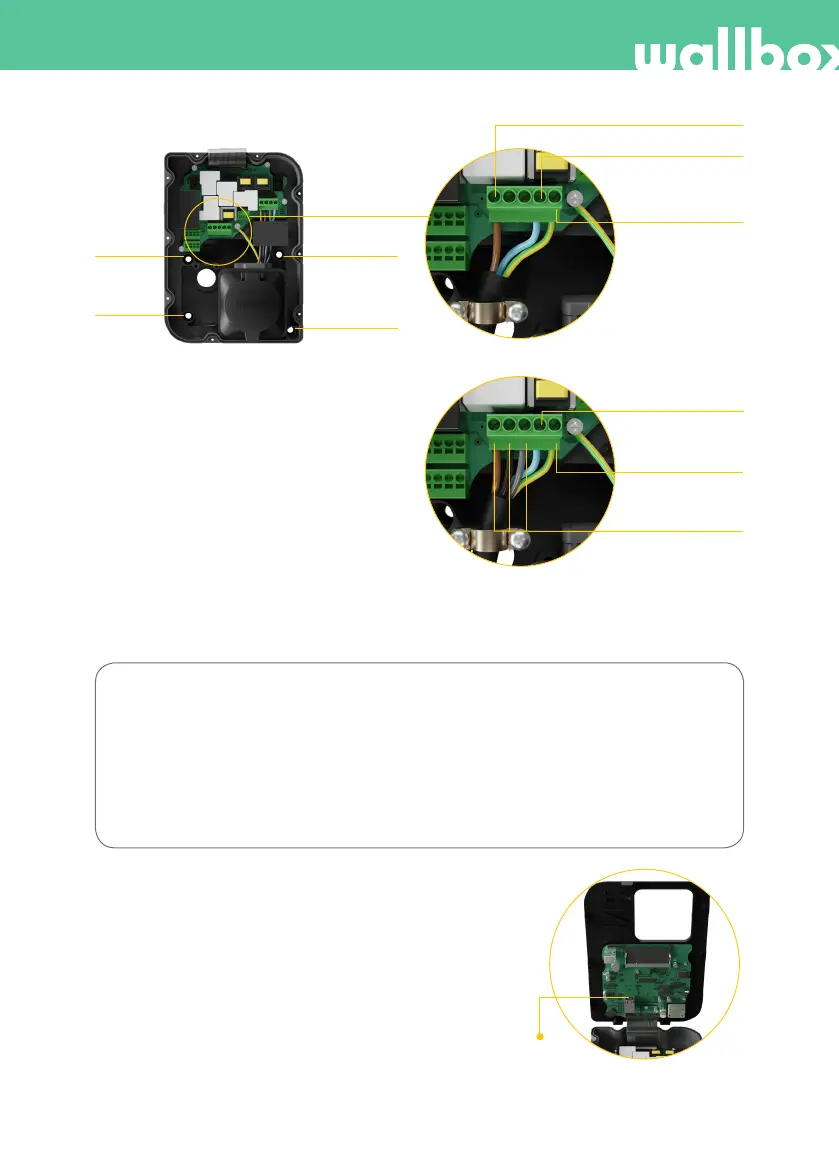
I-4.3: Three-phase setup (3P)
I-4.2: Single-phase setup (1P)
The colours shown are not subject to international
standards. Always check the correct connection.
In the event that the earthing system is IT follow
the configuration steps in 6. Configuring IT
network section.
L1 (Current line)
N (Neutral line)
N (Neutral line)
Protective earth
Protective earth
L1, L2, L3
(Current lines)
2. Screw
1. Screw
4. Screw
3. Screw
I-4.1
In the event that the supply scheme does not include a neutral line connection with a voltage lower than
145 V, follow the next configuration steps:
Bi-phase setup (2P)
From left to right:
L1 (Current line)
N (Current line)
Protective earth
4. Ethernet connection (I-5)
The charger can be connected to the internet
using a built-in Ethernet port installed on the
module cover.
Step 4.1: Insert the Ethernet cable through the
bushing.
Step 4.2: Connect the cable to the Ethernet port.
I-5: Ethernet port