2
TOR.119.--.M.4L Rev. A1
03.11
-
-
-
-
VAR
20
30
20
20
PNEUMATIC CONNECTION OF SOLENOID VALVE TO INFLATABLE SEALS
PNEUMATISCHER ANSCHLUSS DES MAGNETVENTILS AN DEN AUFBLASBAREN DICHTUNGEN
RACCORDEMENT PNEUMATIQUE VANNE A SOLENOIDE AUX JOINTS GONFLABLES
COLLEGAMENTO PNEUMATICO VALVOLA A SOLENOIDE ALLE TENUTE GONFIABILI
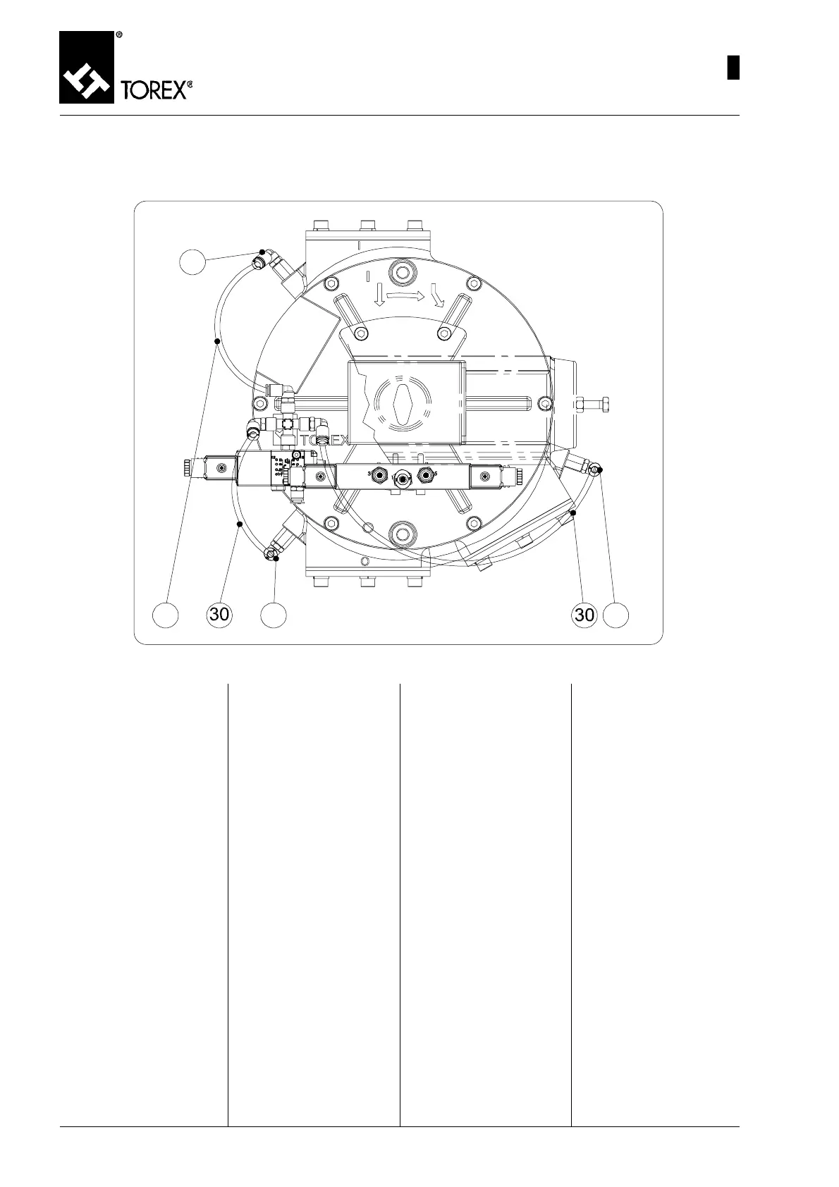
Fig. 46
1) Inserire i 3 Raccordi 90° 1/8”
per tubo diam. 6 mm (pos. 20,
fig. 46) nei 3 innesti aria (pos.
19, fig.16) già inseriti prece-
dentemente per portare l’aria
all’interno delle tenute gonfia-
bili.
2) Tagliare 3 pezzi di lunghezza
adeguata di tubo in RILSAN
diam. 6 mm.
3) Collegare ogni raccordo 90°
1/8” della valvola a solenoide
tenute gonfiabili (pos. 20, fig.
43) con il corrispondente rac-
cordo 90° 1/8” presente in
corrispondenza di ogni boc-
ca (pos. 20, fig. 46). Non Im-
porta l’ordine di collegamento
in quanto le tenute vengono
gonfiate tutte e tre contem-
poraneamente.
4) A questo punto il deviatore è
completamente assemblato.
Per l’utilizzo fare riferimento
ai paragrafi corrispondenti di
questo manuale capitolo 2.
48
MAINTENANCE – INFLATABLE SEALS VALVE ASSEMBLY
WARTUNG - EINBAU DES VENTILS DER AUFBLASBAREN DICHTUNGEN
ENTRETIEN - MONTAGE VANNE JOINTS GONFLABLES
MANUTENZIONE - MONTAGGIO VALVOLA TENUTE GONFIABILI
1) Insert the three 90° 1/8" Un-
ions for the diam. 6 mm tube
(pos. 20, fig. 46) in the three
air unions (pos. 19, Fig.16)
inserted earlier to bring air
into the inflatable seals..
2) Cut three suitable lengths of
6mm diameter Rilsan tube.
3) Connect each 90° 1/8" union
of the inflatable seals sole-
noid valve (pos. 20, Fig. 43)
with the corresponding 90°
1/8" union present at each
inlet (pos. 20, Fig. 46). The
connecting order is not im-
portant as all three seals are
inflated simultaneously.
4) The diverter valve is now
completely assembled.
For use, refer to the corre-
sponding paragraphs in
Chapter 2 of this manual.
1) Die 3 Übergangswinkel 90° 1/
8" für Rohr Durchmesser 6
mm (Pos. 20, Abb. 46) in die 3
Lufteinlässe (Pos. 19, Abb.
16) stecken, die schon
vorher eingesteckt worden
waren, um die Luft in das In-
nere der aufblasbaren Dich-
tungen zu bringen.
2) 3 Stücke passender Länge
vom RILSAN Schlauch mit 6
mm Durchmesser abschnei-
den.
3) Jeden Übergangswinkel 90°
1/8" des Magnetventils der
aufblasbaren Dichtungen
(Pos. 20, Abb. 43) mit dem
entsprechenden Übergangs-
winkel 90° 1/8" verbinden, der
auf jeder Öffnung (Pos. 20,
Abb. 46) vorhanden ist. Die
Reihenfolge, in dem man die
Anschlüsse ausführt, ist egal,
weil alle drei Dichtungen
gleichzeitig aufgeblasen wer-
den.
4) Nun ist die Rohrweiche voll-
kommen zusammengebaut.
Für die Benutzung ist Bezug
auf die entsprechenden Ab-
schnitte dieses Handbuchs
im Kapitel 2 zu nehmen.
1) Introduire les 3 Raccords 90°
1/8" pour tube diam.6 mm
(pos. 20, fig. 46) dans les 3
raccords air (pos. 19, fig. 16)
déjà branchés précédemment
pour amener l’air à l’intérieur
des joints gonflables.
2) Couper 3 morceaux de tube
RILSAN diam 6 mm d’une lon-
gueur appropriée.
3) Brancher chaque raccord
90° 1/8" de la vanne à solé-
noïde joints gonflables (pos.
20, fig. 43) avec le raccord
90° 1/8" correspondant pré-
sent au niveau de chaque
bouche (pos. 20, fig. 46). L’or-
dre de branchement n’est pas
important car les joints sont
gonflés tous les trois 3 en
même temps.
4) La vanne déviatrice est main-
tenant complètement assem-
blée.
Pour l’utilisation faire référen-
ce aux paragraphes corres-
pondants de ce manuel, cha-
pitre 2.
 Loading...