2
03.11
-
-
-
-
TOR.119.--.M.4L Rev. A1
VAR
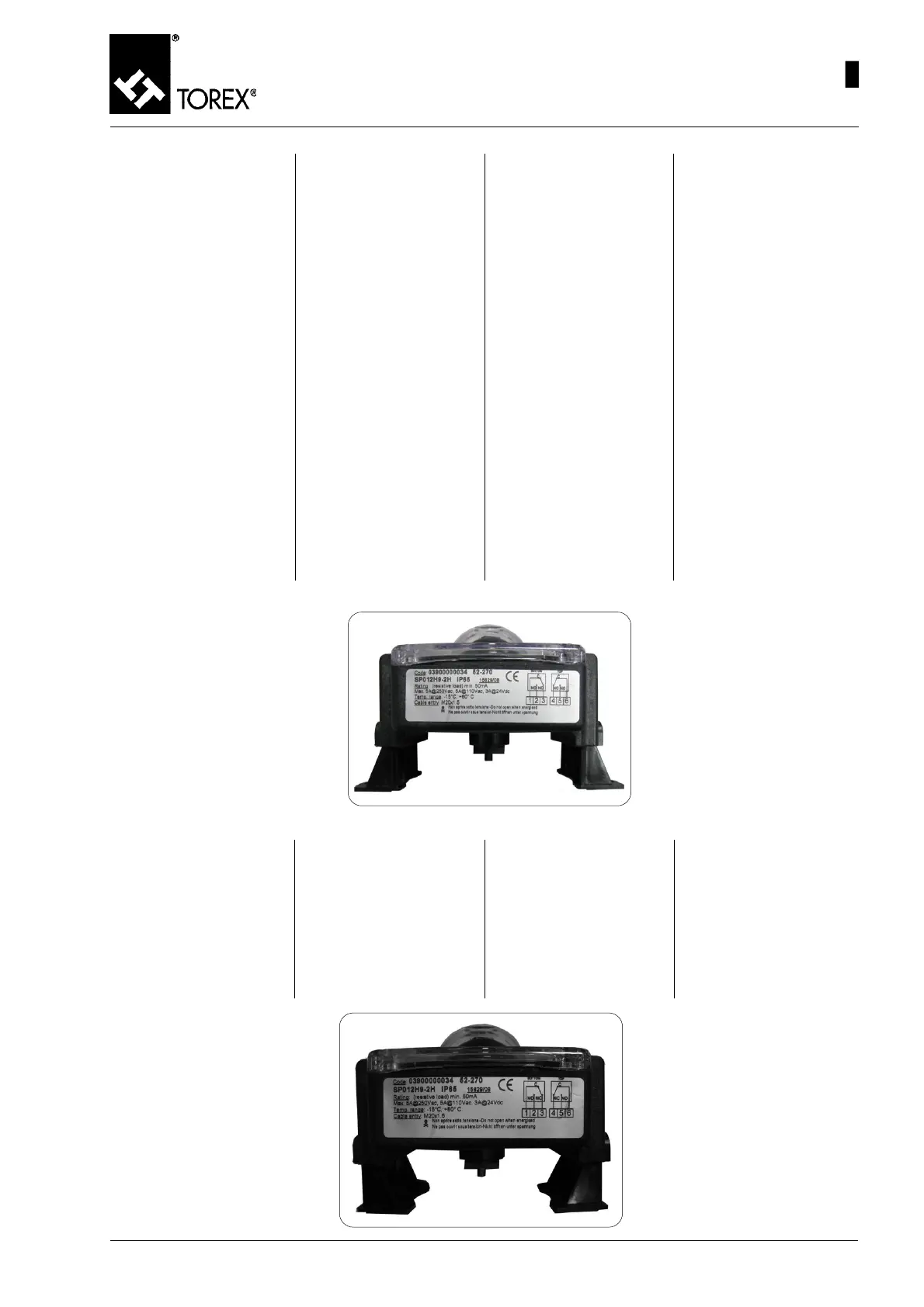
LAYOUT A - SCHALTPLAN A
SCHEMA A - SCHEMA A
• Non superare le limitazioni di
utilizzo dei due finecorsa inter-
ni. Il superamento delle limita-
zioni può causare il danneggia-
mento dei finecorsa stessi, del-
l’attuatore e/o del deviatore.
• Il tappo di protezione dell’in-
gresso cavi forniti a corredo di
ogni box micro serve solo come
protezione durante il trasporto
e non garantisce il grado di pro-
tezione IP65. Sostituirlo in fase
di installazione con pressaca-
vo che garantisca il grado di
protezione richiesto.
MONTAGGIO DEL BOX MICRO
SULL’ATTUATORE
Il Box Micro è completo di Kit per
l’installazione sugli attuatori se-
condo VDI/VDE3845 (130x30 o
80x30). Le staffe sono predispo-
ste per accoppiamento con pi-
gnone attuatore alto 20,30,40 e
50 mm.
1) SCHEMA A (VAR 175 - VAR
200) : Sfilare le due staffe
(pos.10, fig. 52) dal corpo del
Box Micro e fissarle sulla
parte superiore dell’attuatore
secondo lo SCHEMA A utiliz-
zando le 4 viti e rondelle
(pos.11,12 fig. 52).
53
MAINTENANCE – MICRO SWITCH BOX ASSEMBLY - DISASSEMBLY
WARTUNG – EINBAU-AUSBAU DER MIKROSCHALTERBOX
ENTRETIEN - MONTAGE - DEMONTAGE BOX MICRO
MANUTENZIONE - MONTAGGIO-SMONTAGGIO BOX MICRO
• Ne pas dépasser le limites d’uti-
lisation des deux fins de cour-
se internes.
Le dépassement des limites
peut endommager les fins de
course de l’actionneur et/ou de
la vanne déviatrice.
• Le bouchon de protection de
l’entrée des câbles fournis en
équipement de chaque box mi-
cro sert seulement de protec-
tion pendant le tran sport et ne
garantit pas l’indice de protec-
tion IP65. Le remplacer lors de
la mise en place par un serre-
câble garantissant l’indice de
protection requis.
MONTAGE DU BOX MICRO SUR
L’ACTIONNEUR
Le Box Micro est complet de Kit
pour la mise en place sur les
actionneurs VDI/VDE3845
(130x30 ou 80x30). Les brides
sont prévues pour l’accouple-
ment avec pignon actionneur de
20, 30,40 et 50 mm de haut.
• Do not exceed the limits of use
of the two inner limit switches.
Exceeding the limits can cause
damage to the limit switches,
the actuator and/or the divert-
er valve.
• The cables input cover sup-
plied for each micro switch box
is only meant for protection dur-
ing transport and does not
guarantee the IP65 protection.
During installation, replace it
with a cable gland which guar-
antees the required protection.
ASSEMBLING MICRO SWITCH
BOX ON THE ACTUATOR
The Micro switch Box is com-
plete with a Kit for installation on
actuators according to VDI/
VDE3845 (130x30 or 80x30).
The brackets are provided for
coupling with actuator pinion 20,
30, 40 and 50 mm high.
• Die Benutzungsbegrenzungen
der beiden internen Endschal-
ter nicht überschreiten.
Das Überschreiten der Begren-
zungen kann zu Beschädigun-
gen der Endschalter selbst,
des Antriebs und/oder der
Rohrweiche führen.
• Der Schutzstopfen am Eingang
der zum Lieferumfang gehöri-
gen Kabel jeder Mikroschalter-
box dient nur als Transport-
schutz und bietet nicht die
Schutzart IP65. Er wird bei der
Installation durch die Kabelver-
schraubung ersetzt, welche
die erforderliche Schutzart ge-
währleistet.
MONTAGE DER MIKROSCHAL-
TERBOX AUF DEM ANTRIEB
Die Mikroschalterbox wird kom-
plett mit dem Einbausatz auf den
Antrieben nach VDI/VDE3845
(130x30 oder 80x30) geliefert.
Die Bügel eignen sich zur Be-
festigung mit dem Ritzel des An-
triebs mit Höhe von 20, 30, 40
und 50 mm.
Fig. 53
1) SCHALTPLAN A (VAR 175 –
VAR 200) : Die beiden Bügel
(Pos.10, Abb. 52) aus dem
Gehäuse der Mikroschalter-
box herausziehen und sie
auf dem oberen Teil des An-
triebs nach dem SCHALT-
PLAN A befestigen. Dazu die
4 Schrauben und Unterleg-
scheiben (Pos.11,12 Abb. 52)
benutzen.
1) LAYOUT A (VAR 175 – VAR
200): Remove the two brack-
ets (pos.10, Fig. 52) from the
Micro switch Box body and
fix these on the upper part of
the actuator according to
LAYOUT A using the four
screws and washers
(pos.11,12 Fig. 52).
1) SCHEMA A (VAR 175 – VAR
200): Enlever les deux étriers
(pos.10, fig. 52) du corps du
Box Micro et les fixer sur la
partie supérieure de l’action-
neur suivant le SCHEMA A en
utilisant les 4 vis et rondelles
(pos.11,12 fig. 52).
LAYOUT B - SCHALTPLAN B
SCHEMA B - SCHEMA B
Fig. 54
 Loading...