2
03.11
-
-
-
-
TOR.119.--.M.4L Rev. A1
VAR
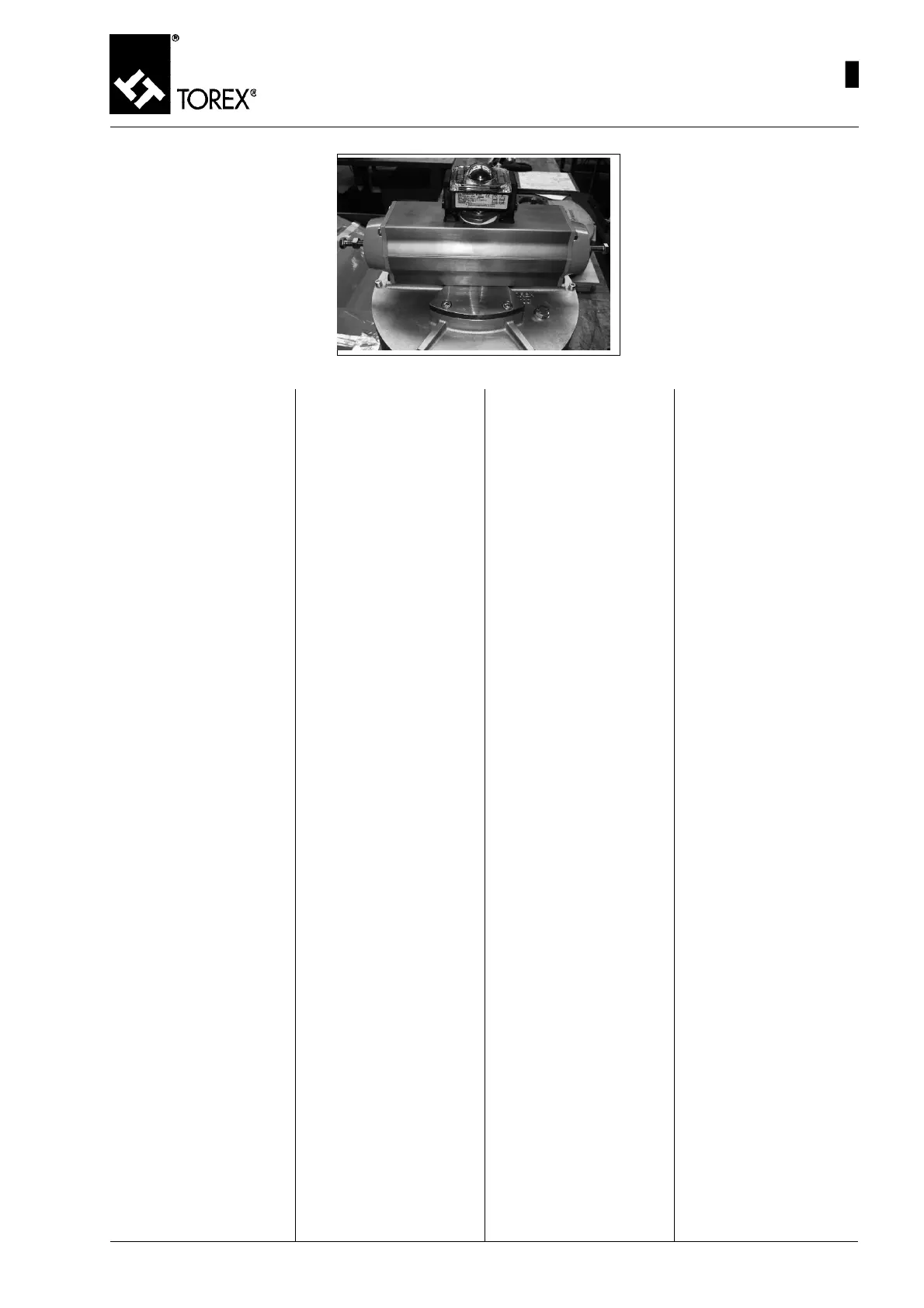
Fig. 57
DEMONTAGE DU BOX MICRO
DE L’ACTIONNEUR
IMPORTANT: Avant de démon-
ter le Box Micro de l’actionneur
couper l’alimentation électrique
du circuit.
1) Dévisser les vis (pos.1, fig.
52) et enlever le couvercle
(pos. 2, fig. 52) et son joint
(pos. 3, fig. 52).
2) En faisant attention à ne pas
endommager les parties inter-
nes, débrancher toutes les
alimentations électriques des
deux borniers (pos. 5, 6, fig.
52).
3) Enlever les 4 vis (pos. 13, fig.
44) qui fixent le corps box
micro aux étriers (pos.10, fig.
52).
4) Tirer vers le haut le corps box
micro et le retirer des étriers
(pos. 10, fig. 42).
5) Dévisser les 4 vis (pos. 11,
fig. 52) et enlever aussi les
étriers (pos.10, fig. 42) du
corps de l’actionneur.
6) Maintenant le box micro est
complètement séparé du
corps de l’actionneur (pos. 9,
fig. 52).
AUSBAU DER MIKROSCHAL-
TERBOX AUS DEM ANTRIEB
WICHTIG: Bevor man die Mikro-
schalterbox vom Antrieb trennt,
die Stromversorgung des Strom-
kreises ausschalten.
1) Die Schrauben (Pos. 1, Abb.
52) losdrehen und den Deckel
(Pos. 2, Abb. 52) mit seiner
Dichtung (Pos. 3, Abb. 52)
entfernen..
2) Darauf achten, dass die inter-
nen Teile nicht beschädigt
werden und alle elektrischen
Versorgungen von den bei-
den Klemmenleisten (Pos. 5,
6, Abb. 52) abtrennen.
3) Die 4 Schrauben (Pos. 13,
Abb. 44), die das Gehäuse
der Mikroschalterbox an den
Bügeln (Pos.10, Abb. 52) be-
festigen, entfernen.
4) Das Gehäuse der Mikroschal-
terbox nach oben ziehen und
von den Bügeln (Pos. 10,
Abb. 42) abziehen.
5) Die 4 Schrauben (Pos. 11,
Abb. 52) losdrehen und auch
die Bügel (Pos.10, Abb. 42)
vom Gehäuse des Antriebs
entfernen.
6) Nun ist die Mikroschalterbox
ganz vom Antriebsgehäuse
(Pos. 9, Abb. 52) getrennt.
DISASSEMBLING MICRO
SWITCH BOX FROM ACTUA-
TOR
IMPORTANT:
Before disassembling the Micro
switch Box from the actuator,
disconnect the electric supply
from the circuit.
1) Slacken the screws (pos.1,
Fig. 52) and remove the cov-
er (pos. 2, Fig. 52) and its
gasket (pos. 3, Fig. 52)
2) Taking care to avoid damag-
ing the inner parts, discon-
nect all the electric supplies
from the two terminal boards
(pos.5, 6, Fig. 52).
3) Remove the four screws (pos.
13, Fig. 44) which fix the mi-
cro switch box body to the
brackets (pos. 10, Fig. 52)
4) Pull the micro switch box body
upwards and remove it from
the brackets (pos. 10, Fig. 42)
5) Remove the four screws (pos.
11, Fig. 52) and remove the
brackets (pos. 10, Fig. 42)
from the actuator body.
6) The micro switch box is now
completely separated from
the actuator body (pos. 9, Fig.
52)
SMONTAGGIO DEL BOX MICRO
DALL’ATTUATORE
IMPORTANTE: Prima di smonta-
re il Box Micro dall’attuatore to-
gliere l’alimentazione elettrica dal
circuito.
1) Svitare le viti (pos.1, fig. 52)
e togliere il coperchio (pos.
2, fig. 52) e la sua guarnizio-
ne (pos. 3, fig. 52)
2) Facendo bene attenzione a
non danneggiare le parti in-
terne, scollegare tutte le ali-
mentazioni elettriche dalle due
morsettiere (pos. 5, 6, fig.
52).
3) Togliere le 4 viti (pos. 13, fig.
44) che fissano il corpo box
micro alle staffe (pos. 10, fig.
52)
4) Tirare verso l’alto il corpo box
micro e sfilarlo dalle staffe
(pos. 10, fig. 42)
5) Svitare le 4 viti (pos. 11, fig.
52) e togliere anche le staffe
(pos. 10, fig. 42) dal corpo
dell’attuatore.
6) A questo punto il box micro è
completamente separato dal
corpo dell’attuatore (pos. 9,
fig. 52)
55
MAINTENANCE – MICRO SWITCH BOX ASSEMBLY - DISASSEMBLY
WARTUNG – EINBAU-AUSBAU DER MIKROSCHALTERBOX
ENTRETIEN - MONTAGE - DEMONTAGE BOX MICRO
MANUTENZIONE - MONTAGGIO-SMONTAGGIO BOX MICRO
 Loading...