Service
Manual
OD-101-15
9
Circuit Description
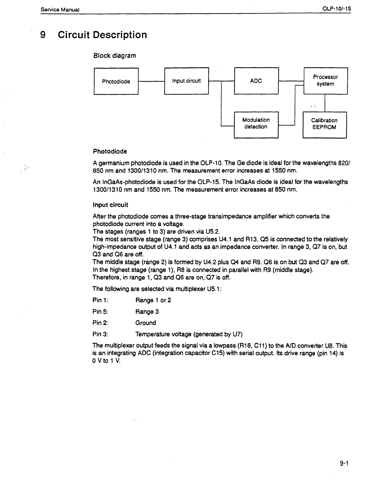
Block diagram
Modulation Calibration
detection
Photodiode
P
hotodiode
ADC
Processor
Input circuit
-
system
-
A germanium photodiode is used in the
OLP-10.
The Ge diode is ideal for the wavelengths
8201
850
nm and
l3OOIl3lO
nm. The measurement error increases at
1550
nm.
.
.
An InGaAs-photodiode is used for the
OLP-15.
The InGaAs diode is ideal for the wavelengths
130011310
nm and
1550
nm. The measurement error increases at
850
nm.
lnput circuit
After the photodiode comes a three-stage transimpedance amplifier which converts the
photodiode current into a voltage.
The stages (ranges
1
to
3)
are driven via
U5.2.
The most sensitive stage (range
3)
comprises
U4.1
and
R13. Q5
is connected to the relatively
high-impedance output of
U4.1
and acts as an impedance converter. In range
3, Q7
is on, but
Q3
and
Q6
are off.
The middle stage (range
2)
is formed by
U4.2
plus
Q4
and
R9. Q6
is on but
Q3
and
Q7
are off.
In the highest stage (range
I), R8
is connected in parallel with
R9
(middle stage).
Therefore, in range
1, Q3
and
Q6
are on,
Q7
is off.
The following are selected via multiplexer
U5.1:
Pin
1:
Range
1
or
2
Pin
5:
Range
3
Pin
2:
Ground
Pin
3:
Temperature voltage (generated by
U7)
The multiplexer output feeds the signal via a lowpass
(R18, C11)
to the
AID
converter
U8.
This
is an integrating
ADC
(integration capacitor
C15)
with serial output. Its drive range (pin
14)
is
0
v
to
1
v.
Artisan Technology Group - Quality Instrumentation ... Guaranteed | (888) 88-SOURCE | www.artisantg.com
 Loading...