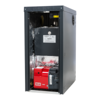
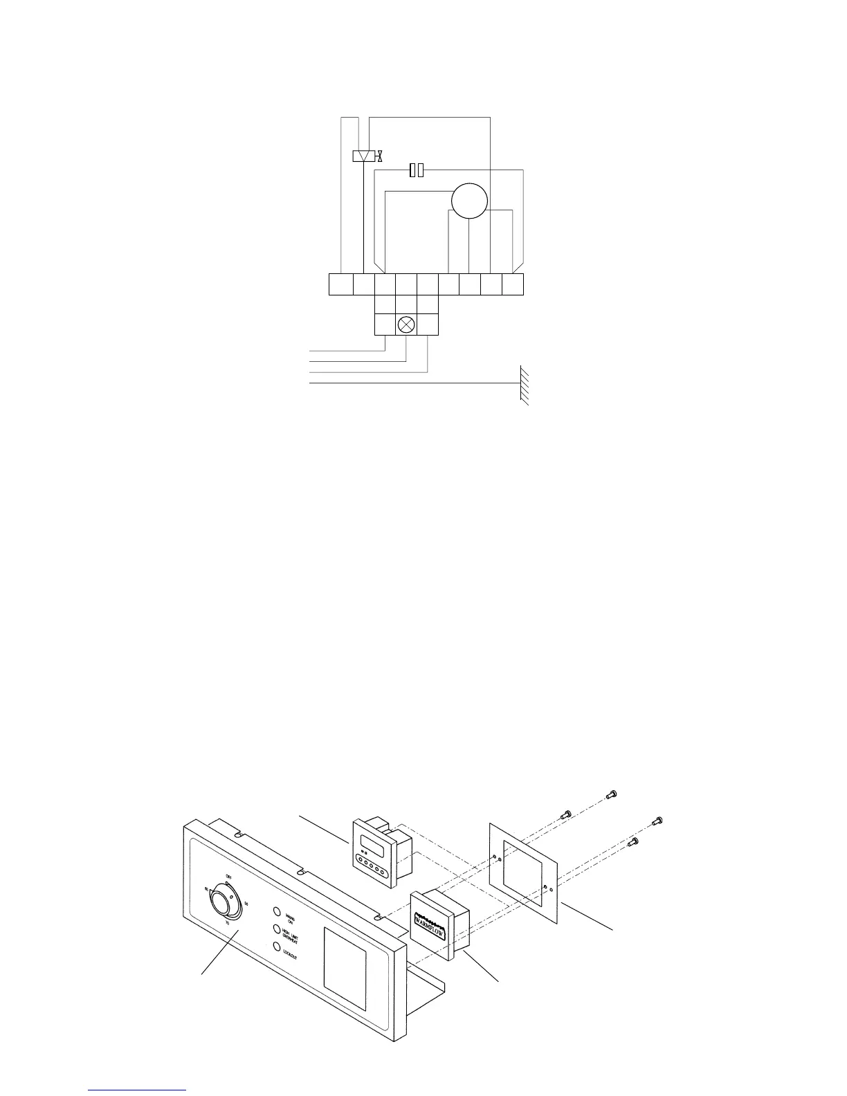
CONTROL PANEL
BLANKING PLATE
BLANKING PLATE/
PROGRAMMER
BRACKET
OPITIONAL
PROGRAMMER
5.5 Installation of Warmflow Optional Programmer (Goldbird Boilers only)
1. Isolate power supply.
2. Remove top casing (4 studs) and control panel cover (1 screw).
3. Remove 2 screws securing blanking plate/programmer bracket. Remove bracket and
blanking plate from the control panel.
4. Disconnect the blanking plate from bracket (2 screws).
5. Feed programmer harness through the hole in the bracket. The programmer is secured
to the bracket with 2 screws.
6. Remove loop ‘A’ between 15 and 16 on the wiring block.
7. Connect the 6 pin plug into the socket.
8. Locate the programmer into the hole in the facia and secure the bracket to the control
panel (2 screws).
9. Set the time switch on the rear of the programmer to ‘G’ or ‘P’ (see programmer
instructions).
10. Replace the control panel cover and reconnect electrical supply.
11. Operational instructions are included in this handbook.
Page 16