©2011 Warn Industries, Inc.WARN® and the WARN logo are trademarks of Warn Industries Inc. 5 88126A0
INSTALLATION INSTRUCTIONS
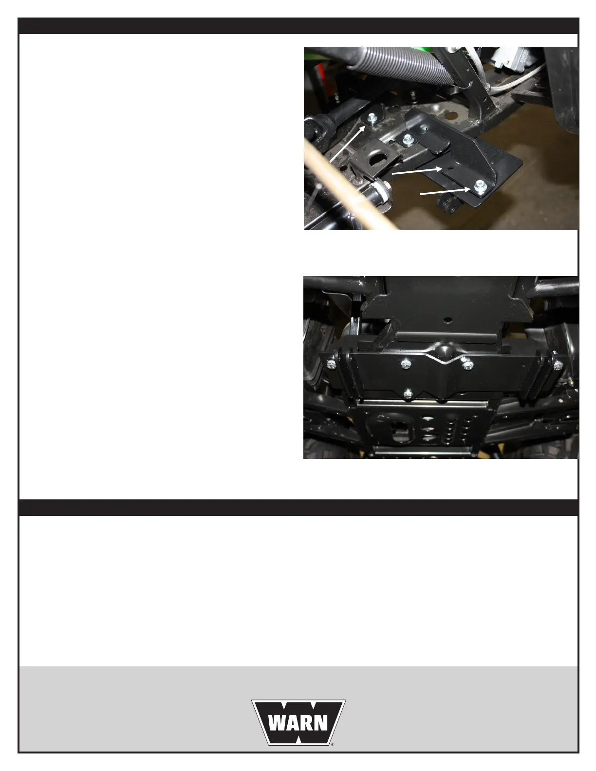
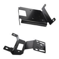
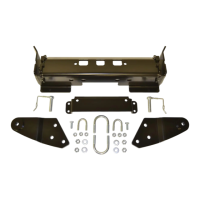
4. Place the left hand bracket over the frame and line the
holes up with the plow mount. Place the three remaining
hex head bolts along with three at washers up through the
three holes. Then put three at washers along with the lock
nuts on the bolts. See gure 4
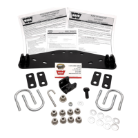
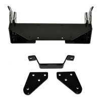
5. Tighten the bolt with the large black washer rst. Then you
can tighten the rest of the fasteners at this time. Try to
tighten the rest of the fasteners evenly, and not so much
that you distort the mount to much. See gure 5.
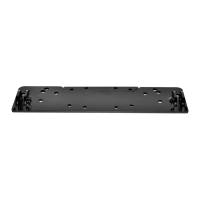
Figure 4 - Mark Plow Mount Slots
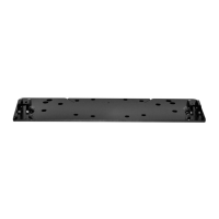
Figure 5 - Remove Plastic Skid Plate
MAINTENANCE / CARE
• Inspectallmetalpartsontheplow,plowmount,andrelatedhardware.Replaceallpartsthatappearrustedordeformed
priortouse.
• Inspectallnutsandboltsontheplow,plowmount,andrelatedhardwarepriortoeachuse.Tightenallnutsandboltsthat
appeartobeloose.Stripped,fractured,orbentboltsornutsneedtobereplacedimmediately.
• Checkallcablespriortouse.Replacecablesthatarewornorfrayed.
• Checkallmovingandrotatingparts.Removedebristhatmayinhibitthepartfrommovingfreely.
CARELESS INSTALLATION AND OPERATION CAN RESULT IN SERIOUS INJURY OR EQUIPMENT DAMAGE. READ AND UNDERSTAND ALL
SAFETY PRECAUTIONS AND OPERATING INSTRUCTIONS BEFORE INSTALLING AND OPERATING THIS PRODUCT.