EasyManua.ls Logo

Warner RF FMT5.0 Series - User Manual

Default Icon
7 pages
Print Icon
To Next Page IconTo Next Page
Loading...
Operation
All m
enu screenshots are take from FMT5
The m
Initial preparation work
First set up the antenna cable
and connect it to the transmitter's RFOUT port, then plug the power
cord into the transmit
ter's power outlet. Next,
the outlet is divided into two channels. Connection is complete, please turn on the transmitter panel
POWER button, the device starts.
Transmitter Boot I
nterface
Model / equipment name / manufacturer information
FMT5.0 Series
Manual
enu screenshots are take from FMT5
-
150H , others FMT 5.0 series products are with the same
operation, just the power is different
Version updated frequently
The m
anual may differ with the latest model.
and connect it to the transmitter's RFOUT port, then plug the power
ter's power outlet. Next,
insert the audio cable
to the XLR
the outlet is divided into two channels. Connection is complete, please turn on the transmitter panel
POWER button, the device starts.
nterface
Model / equipment name / manufacturer information
150H , others FMT 5.0 series products are with the same
and connect it to the transmitter's RFOUT port, then plug the power
to the XLR
header or RCA outlet,
the outlet is divided into two channels. Connection is complete, please turn on the transmitter panel
Question and Answer IconNeed help?

Do you have a question about the Warner RF FMT5.0 Series and is the answer not in the manual?

Summary

FMT5.0 Series Operation Manual Overview

FMT5.0 Series General Description

General description of the FMT5.0 series operation and variations based on power.

Front Panel Controls and Indicators

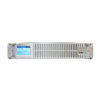
Labeled diagram of the FMT5.0 series front panel controls and indicators.

Rear Panel Connectivity Ports

Labeled diagram of the FMT5.0 series rear panel connectivity options.

Initial Setup and Boot Process

Initial Preparation Work

Steps to connect the antenna cable, power cord, and audio cables before powering on.

Transmitter Boot Interface

Displays model name, equipment type, and manufacturer details during the boot sequence.

Transmitter Boot Configuration

The transmitter loads default settings or last configuration during the boot process.

PLL Lock Wait State

The system waits for the Phase-Locked Loop to stabilize after frequency changes.

Main Interface and Menu Navigation

Main Interface Parameters

Explanation of key operational parameters displayed on the main screen.

Navigating to Menu Settings

How to enter the menu system from the main interface using the control knob.

Menu 1: Frequency Setting

Adjusting Operating Frequency

Procedure to set and confirm the desired operating frequency.

Confirming Frequency Settings

Process of confirming frequency changes and waiting for PLL lock.

Menu 2: RF Power Setting

Adjusting RF Output Power

How to set and confirm the desired RF power output.

Understanding Power Parameters

Explanation of current RF power, drive, and VSWR values.

Menu 3: Signal Modulation Setting

Selecting Modulation Mode

Choosing between stereo, mono, or external modulation inputs.

Available Signal Modes

Details on Stereo, Mono, and External Modulation input options.

Confirming Signal Mode

How to select and confirm the chosen signal mode.

Menu 4: Audio Pre-emphasis Setting

Adjusting Pre-emphasis Levels

Setting the pre-emphasis values (e.g., 0us, 50us, 75us).

Understanding Pre-emphasis Values

Explains current and setting options for audio pre-emphasis.

Menu 5: Audio Gain Setting

Setting Left;Right Channel Gain

Adjusting audio gain for independent or combined channels.

Muting Audio Channels

Option to mute audio output for specific channels.

Menu 6: External Modulation Gain Setting

Adjusting External Modulation Gain

Setting the gain level for external modulation sources.

Muting External Modulation

Option to mute the external modulation signal.

Menu 7: Network Settings

Network Option Status

Indicates if the network option is installed or not.

Menu 8: Exit Menu

Returning to Main Interface

How to exit all menus and return to the main operational screen.

System Sleep Mode

Engaging System Sleep

How to put the system into a low-power sleep mode from the main menu.

System Alarm Prompts

VSWR Too High Warning

Alert for high Voltage Standing Wave Ratio, advises checking antenna and cable.

Temperature Too High Warning

Alert for high internal temperature, advises room cleanliness and cooling.

Overview

This document describes the FMT5.0 Series FM broadcast transmitter, specifically referencing the FMT5-150H model. The manual outlines the device's functions, operational procedures, and maintenance features.

Function Description

The FMT5.0 Series is an FM broadcast transmitter designed for professional use. Its primary function is to modulate an audio signal onto a radio frequency carrier for broadcast. The device features a comprehensive display that provides real-time operational parameters, including:

  • Frequency (F): The current operating frequency in MHz.
  • Forward Power (POW): The power being transmitted, measured in Watts.
  • Voltage Standing Wave Ratio (VSWR): An indicator of how efficiently radio-frequency power is transmitted from a power source, through a transmission line, into a load. A VSWR of 1.0 indicates a perfect match.
  • VU Meter (L/R): Displays the audio levels for the left and right channels, indicating modulation depth.
  • Temperature (TEMP): The internal temperature of the amplifier, measured in Celsius.
  • Drive (DRIVE): The output ratio of the drive stage, indicating the power level of the pre-amplifier.

The transmitter supports various audio input types:

  • Digital Audio: AES/EBU and Coaxial inputs.
  • Analog Audio: Left and right channel inputs via XLR or RCA.
  • SCA/RDS Input: For subcarrier and Radio Data System signals.

The device allows for flexible signal modulation settings, including:

  • STEREO + EXT MOD: Stereo input with external modulation.
  • MONO + EXT MOD: Mono input with external modulation.
  • EXT MOD: External modulation only.
  • STEREO: Stereo input only.
  • MONO: Mono input only.

Important Technical Specifications

While specific numerical values for all technical specifications are not exhaustively listed, the manual highlights several key adjustable parameters and their ranges:

  • Frequency Range: The system default frequency is 98MHz, but the device supports a range from 87.50MHz to 108.00MHz, allowing for user-defined frequency settings.
  • RF Power: The transmitter can output up to 150.0 Watts, with the ability to adjust the power setting from 000.0 Watts to 150.0 Watts. The drive level (e.g., 0623 for 150W output) is also displayed.
  • Audio Pre-emphasis: Adjustable settings include 0µs, 50µs, and 75µs, allowing compliance with different broadcast standards.
  • Audio Gain: The gain for both left and right audio channels can be adjusted in real-time, typically from 0.0dB, with a mute option available.
  • External Modulation Gain: Similar to audio gain, the external modulation gain can be adjusted in real-time from 0.0dB, with a mute option.
  • Power Supply: The device operates within an AC range of 100-250V.
  • Connectivity: Includes RS-232 port for data communication, digital audio inputs (AES/EBU, Coaxial), analog audio inputs (XLR, RCA), and SCA/RDS input.

Usage Features

The FMT5.0 Series transmitter is designed for ease of use with a rotary knob for navigation and selection.

Initial Setup:

  1. Connect the antenna cable to the RFOUT port.
  2. Plug the power cord into the power outlet.
  3. Insert audio cables into the XLR or RCA outlets (two channels).
  4. Turn on the POWER button on the front panel.

Boot Process: Upon startup, the device displays a boot interface showing the model, equipment name, and manufacturer (FMT5.0-150H FM broadcast transmitter, Warner RF Electronic Equipment Co., Ltd.). It then proceeds to either "Transmitter boot. [Last config]" or "Transmitter boot. [Default config]".

  • Last config: Loads the settings from the previous shutdown.
  • Default config: Loads system defaults (98MHz, power ON, Stereo + external modulation, 0 audio pre-emphasis, 0dB volume gain).
  • A "PLL lock" waiting screen appears during frequency stabilization (2-10 seconds).

Main Interface: The main interface displays real-time operational parameters: F (frequency), POW (forward power), VSWR, L (left channel level), DRIVE (amplifier push), TEMP (amplifier temperature), MOD (modulation level), and R (right channel level).

Menu Navigation: A short press of the knob enters the menu settings. Turning the knob selects different menu options, and a short press confirms the selection.

Key Adjustable Settings:

  • Menu 1: Frequency Setting: Adjusts the operating frequency. The device will re-lock the PLL after a frequency change.
  • Menu 2: RF Power Setting: Adjusts the output power.
  • Menu 3: Signal Modulation Setting: Selects the audio input and modulation mode (Stereo, Mono, External Modulation).
  • Menu 4: Audio Pre-emphasis Setting: Configures the pre-emphasis curve (0µs, 50µs, 75µs).
  • Menu 5: Audio Gain Setting: Adjusts the audio input gain for left, right, or both channels. Users can set levels or mute the audio.
  • Menu 6: External Modulation Gain Setting: Adjusts the gain for external modulation input, with a mute option.
  • Menu 7: Network Settings: (If installed) Allows configuration of network options. The manual indicates "Network option not installed" if the feature is absent.
  • Menu 8: Exit: Returns to the main interface.

System Sleep: A long press of the knob from the main menu page puts the system into sleep mode. A short press exits hibernation.

Maintenance Features

The manual provides crucial information regarding system alarms and environmental considerations, which are vital for maintaining the device's longevity and performance.

System Alarm Prompts: The device features an alarm system to alert users to critical operational issues:

  • "Warning: U.S.W.R is too high! Please check the antenna and cable.": This alarm indicates a high Voltage Standing Wave Ratio, suggesting a mismatch or fault in the antenna system or cabling. Immediate action is required to prevent damage to the transmitter's final amplifier stage.
  • "Warning: temperature is too high! Please keep the dust, free space and <40℃": This alarm triggers when the internal temperature exceeds 70°C. It emphasizes the importance of maintaining a clean environment, ensuring adequate ventilation (free space around the unit), and keeping the ambient room temperature below 40°C to prevent overheating and potential damage.

Environmental Considerations:

  • Temperature Management: The warning about high temperature highlights the need for proper cooling and a suitable operating environment. Regular cleaning to prevent dust accumulation is implied to ensure efficient heat dissipation.
  • Antenna System Integrity: The VSWR warning underscores the importance of a well-matched and properly connected antenna system. Regular inspection of the antenna and cables is essential for optimal performance and to avoid transmitter damage.

The manual, while concise, provides a clear guide for operating and maintaining the FMT5.0 Series FM broadcast transmitter, ensuring reliable performance and addressing potential issues through its alarm system.

Warner RF FMT5.0 Series Specifications

General IconGeneral
BrandWarner RF
ModelFMT5.0 Series
CategoryTransmitter
LanguageEnglish

Related product manuals