s1fmdl1sm-REV1207 Model S1F Metallic Page 16
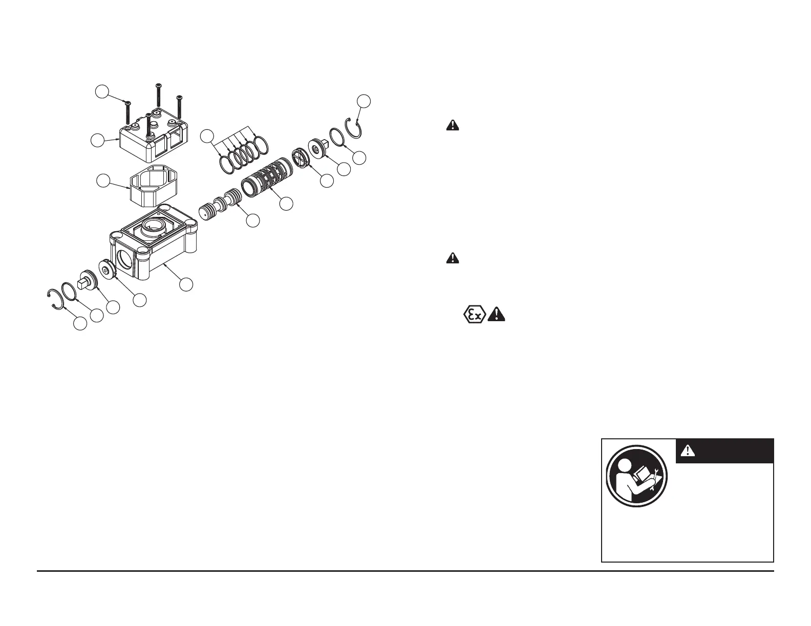
Air Valve Assembly Drawing, Parts List
AIR VALVE ASSEMBLY PARTS LIST
Item Part Number Description Qty
1 031-140-001 Air Valve Assembly 1
1-A 031-139-000 Sleeve and Spool Set 1
1-B 095-094-559 Body, Air Valve 1
1-C 132-029-552 Bumper 2
1-D 165-096-559 Cap, Muffler 1
1-E 165-115-552 Cap, End 2
1-F 530-028-550 Mufer 1
1-G 560-020-360 O-Ring 8
1-H 675-044-115 Ring, Retaining 2
1-J 710-015-115 Screw, Self Tapping 4
For Pumps with Alternate Mesh or Piped Exhaust:
1 031-141-001 Air Valve Assembly 1
(includes all items on 031-140-001 minus 1-D, 1-F, & 1-J)
1-J
1-D
1-F
1-G
1-H
1-G
1-E
1-C
1-A
1-A
1-B
1-C
1-E
1-G
1-H
(Use With Cast Iron Centers Only)
AIR DISTRIBUTION VALVE WITH
STROKE INDICATOR OPTION
SERVICING
To service the air valve first shut off the
compressed air supply, bleed the pressure
from the pump, and disconnect the air
supply line from the pump.
Step #1: See COMPOSITE REPAIR PARTS
DRAWING.
Using a 5/16" Allen wrench, remove the
four hex socket capscrews (item 12) and four
flat washers (item 39). Remove the air valve
assembly from the pump.
Remove and inspect gasket (item 19)
for cracks or damage. Replace gasket if
needed.
Step #2: Disassembly of the air valve.
To access the inter nal air valve
components first remove the two retaining
rings (item 1-H) from each end of the air
valve assembly using clip ring pliers.
Next remove the two end caps (item
1-E). Inspect the o-ring (items 1-G) for cuts
or wear. Replace the o-rings if necessary.
Remove the spool (part of item 1-A)
from the sleeve. Be careful not to scratch
or damage the outer diameter of the spool.
Wipe spool with a soft cloth and inspect for
scratches or wear.
Inspect the inner diameter of the sleeve
(part of item 1-A) for dirt, scratches, or other
contaminants. Remove the sleeve if needed
and replace with a new sleeve and spool
set(item 1-A).
Step #3: Reassembly of the air valve.
Install one end cap (item 1-E) with
o-ring (item 1-G) into one end of the air
valve body (item 1-B). Install one retaining
ring (item 1-H), into the groove on the same
end.
Remove the new sleeve and spool set
(item 1-A) from the plastic bag. Carefully
remove the spool from the sleeve. Install the
six o-rings (item 1-G) into the six grooves on
the sleeve. Apply a light coating of grease to
the o-rings before installing the sleeve into
the valve body (item 1-B). Align the slots in
the sleeve with the slots in the valve body.
Insert the spool into the sleeve. Be careful
not to scratch or damage the spool during
installation. Push the spool in until it touches
the bumper on the opposite end.
Install the remaining end cap with
o-rings and retaining ring.
Fa st en th e a ir val ve a ss em bly
(item 1) and gasket (item 19) to the pump.
Connect the compressed air line to the
pump. Remove the safety clip. The pump is
now ready for operation.
Read these instructions
completely, before in-
stallation and start-up.
It is the responsibility of
the purchaser to retain
this manual for reference. Failure to
comply with the recommendations stated
in this manual will damage the pump, and
void factory warranty.
IMPORTANT
ATEX Compliant
 Loading...